7
ENGLISH
5. Activate a DHW request as follows:
heating only boilers connected to an external storage tank: activate
the thermostat on the storage tank;
6. Carry on with the sequence until only water leaks out of the manual
air vent valve, and the air ow has stopped. Close the manual air vent
valve.
7. Check the system pressure level is correct (the ideal level is 1 bar).
8. Turn off the system lling tap.
9. Turn on the gas tap and ignite the boiler.
3.11 Flue gas discharge and air suction
Observe local legislation regarding ue gas discharge.
Flue gases are discharged
from a centrifugal fan located inside the combus-
tion chamber and the control board constantly checks that this is working
correctly. The boiler is supplied without the ue gas discharge/air suction kit,
since it is possible to use the accessories for appliance with a forced draught
sealed chamber that better adapts to the installation characteristics.
For ue gas extraction and the restoration of boiler combustion air, it is essen-
tial to only use certied piping. Connection must be carried out correctly as in-
dicated in the instructions supplied as standard with the ue gas
accessories.
Multiple appliances can be connected to a single smoke pipe provided that
each is a sealed chamber-type appliance. The boiler is a Type C appliance
(sealed chamber), and must therefore have a safe connection to the ue
gas discharge pipe and to the combustion air suction pipe; these both carry
their contents outside, and are essential for the operation of the appliance.
POSSIBLEOUTLETCONFIGURATIONS(FIG.24)
B23P/B53P Suction indoors and discharge outdoors
C13-C13x Discharge via concentric wall outlet. The pipes may leave the
boiler independently, but the outlets must be concentric or sufciently close
together to be subjected to similar wind conditions (within 50 cm)
C23 Discharge via concentric outlet in common smoke pipe (suction and
discharge in the same pipe)
C33-C33x Discharge via concentric roof outlet. Outlets as for C13
C43-C43x Discharge and suction in common separate smoke pipes, but
subjected to similar wind conditions
C53-C53x Separate discharge and suction lines on wall or roof and in areas
with different pressures. The discharge and suction lines must never be
positioned on opposite walls
C63-C63x Discharge and suction lines using pipes marketed and certied
separately (1856/1)
C83-C83x Discharge via single or common smoke pipe and wall suction line
C93-C93x Discharge on roof (similar to C33) and air suction from a single
existing smoke pipe
“FORCED OPEN” INSTALLATION(TYPEB23P/B53P)
Fluegasdischargepipeø80mm(g.20)
The ue gas discharge pipe can be directed to the most suitable direction
according to installation requirements. For installation, follow the instruc-
tions supplied with the kit. In this conguration, the boiler is connected to
the ue gas discharge pipe (ø 80 mm) through an adaptor (ø 60-80 mm).
The B23P/B53P conguration is forbitten in case of installation in
pressurised collective chimney (3CEp).
In this case, the combustion air is picked up from the boiler instal-
lation room (which must be a suitable technical room with proper
ventilation).
Uninsulated ue discharge outlet pipes are potential sources of danger.
Arrange the ue gas discharge pipe so it slopes by 3° towards the boiler.
The boiler automatically adapts the purging to the type of installation
and the length of the pipe.
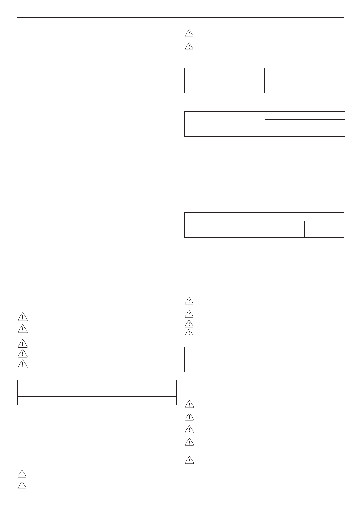
maximum length* of the ue gas
discharge pipe ø 80 mm
pressure drop
45° bend 90° bend
70 m 1 m 1,5 m
*“Straight length” means without bends, drainage terminals or joints.
“SEALED”INSTALLATION(TYPEC)
The boiler must be connected to concentric or twin ue gas discharge pipes
and air suction pipes, both leading outdoors. The boiler must not be oper-
ated without them.
Concentricpipes(ø60-100mm)(g.21)
The concentric pipes can be placed in the most suitable direction according
to installation requirements, complying with the maximum lengths indicated
in the table.
Arrange the ue gas discharge pipe so it slopes by 3° towards the
boiler.
Non-insulated outlet pipes are potential sources of danger.
The boiler automatically adapts the purging to the type of installation
and the length of the pipe.
Do not obstruct or choke the combustion air suction pipe in any way.
For installation, follow the instructions supplied with the kit.
Horizontal
straight length *
concentric pipe ø 60-100 mm
pressure drop
45° bend 90° bend
5,85 m 1,3 m 1,6 m
*“Straight length” means without bends, drainage terminals or joints.
Vertical
straight length *
concentric pipe ø 60-100 mm
pressure drop
45° bend 90° bend
6,85 m 1,3 m 1,6 m
*“Straight length” means without bends, drainage terminals or joints.
If the boiler must be installed with drainage below, use the special elbow (kit
available on request – see Parts Catalogue).
In this type of installation, the inner pipe of the elbow must be cut at the
point shown in g. 22 to allow the elbow itself to be inserted more easily into
the ue gas discharge on the boiler.
Concentricpipes(ø80-125)
For this conguration, the special adaptor kit must be tted. The concentric
pipes can face in the direction most suitable for installation requirements.
For installation, follow the instructions supplied with the specic condensing
boilers kits.
straight length *
concentric pipe ø 80-125 mm
pressure drop
45° bend 90° bend
15,3 m 1,0 m 1,5 m
*“Straight length” means without bends, drainage terminals or joints.
Twinpipes(ø80mm)(g.23)
The twin pipes can face in the direction most suited to the installation re-
quirements. For installation, follow the instructions supplied with the spe-
cic accessory kit for condensing boilers.
To use the combustion air suction pipe, one of the two inlets (A and B) must
be selected. Remove the closure plug which is xed using screws, and use
the specic adaptor relating to the inlet selected (C air inlet adaptor ø 80 - D
air inlet adaptor from ø 60 to ø 80) available as an accessory.
Arrange the ue gas discharge pipe so it slopes by 3° towards the
boiler.
The boiler automatically adapts the purging to the type of installation and
the length of the pipes. Do not obstruct or choke the pipes in any way.
Refer to the graphs to nd the maximum lengths of the single pipe.
The use of longer pipes reduces the boiler output.
maximum straight length *
twin pipes ø 80 mm
pressure drop
45° bend 90° bend
45+45 m 1,0 m 1,5 m
*“Straight length” means without bends, drainage terminals or joints.
PRESSURISED COLLECTIVE CHIMNEY 3CEp
3CEp installations are available only with the dedicated accessory
(optional).
The B23P/B53P conguration is forbitten in case of installation in
pressurised collective chimney.
Maximum pressure of the pressurised collective chimney must not
exceed the 35 Pascal.
Maintenance in case of pressurised collective chimney must be
performed as indicated in the specic chapter “Maintenance in-
structions”.
For 3CEp installations with dedicated accessory, it is necessary
change the setting of minimum fan speed according the accessory
instructions.


Diskutieren Sie über dieses Produkt mit
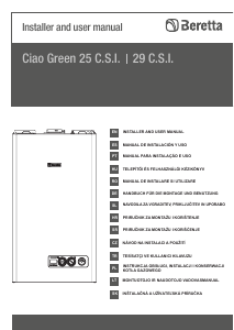
Hier können Sie uns Ihre Meinung zu Beretta Ciao Green 25 RSI Zentralheizungskessel mitteilen. Wenn Sie eine Frage haben, lesen Sie zunächst das Bedienungsanleitung sorgfältig durch. Die Anforderung eines Bedienungsanleitung kann über unser Kontaktformular erfolgen.
Antworten | Das war hilfreich (0) (Übersetzt von Google)
Antworten | Das war hilfreich (0) (Übersetzt von Google)
Antworten | Das war hilfreich (0) (Übersetzt von Google)
Antworten | Das war hilfreich (0) (Übersetzt von Google)