6
CIAO GREEN R.S.I.
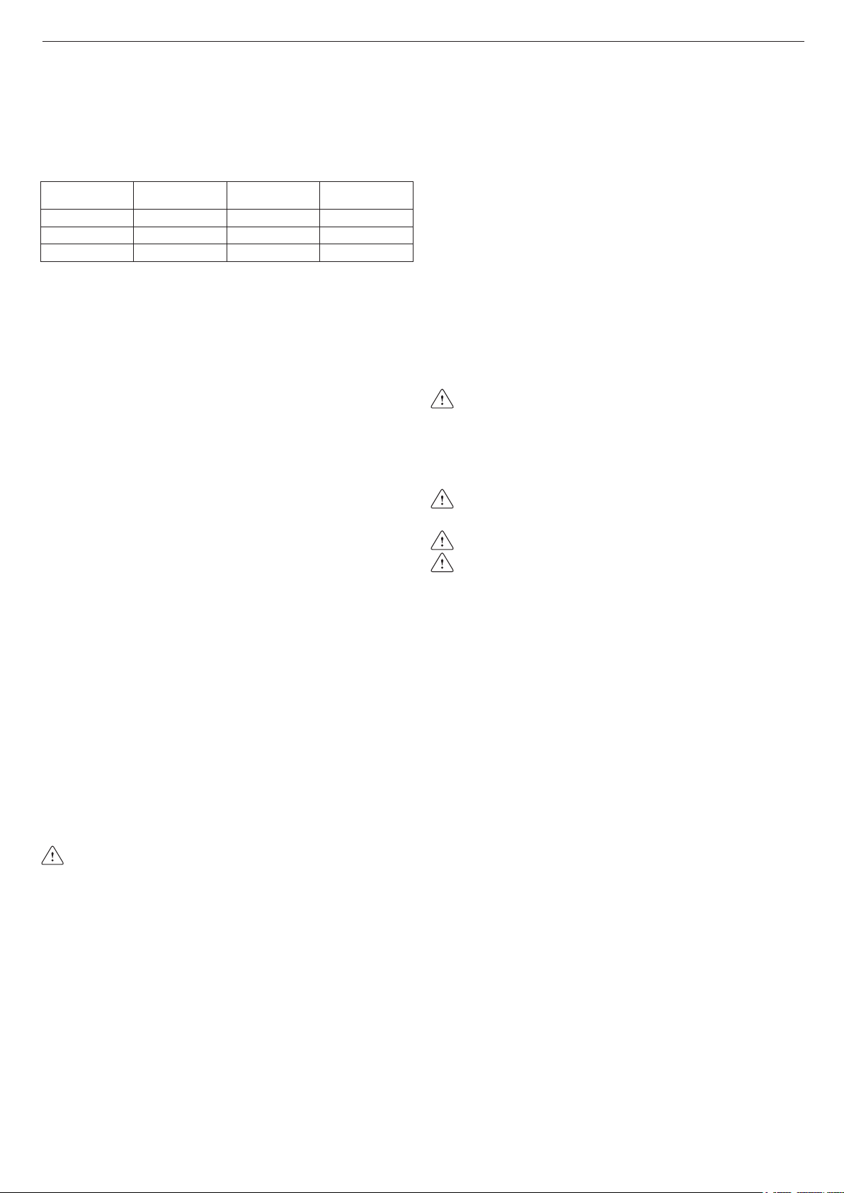
3.2 Cleaning the system and characteristics of the
heating circuit water
In the case of a new installation or replacement of the boiler, it is necessary
to clean the heating system.
To ensure the device works well, top up the additives and/or chemical treat-
ments (e.g. antifreeze liquids, lming agents, etc.) and check the param-
eters in the table are within the values indicated.
Parameters Unit of
measurement
Hot water
circuit
Filling
water
pH value 7–8
-
Hardness °F
-
15–20
Appearance
- clear
3.3 Securing the boiler to the wall and hydraulic
connections
To secure the boiler to the wall, use the crossbar (g. 10) provided in the box.
The position and size of the hydraulic connections are indicated below:
M Heating outlet 3/4”
MB Water tank delivery 3/4”
G Gas connection 3/4”
RB Water tank return 3/4”
R Heating return line 3/4”
3.4Installationoftheexternalsensor(g.11)
The correct operation of the external sensor is fundamental for the good
operation of the climate control.
INSTALLING AND CONNECTING THE EXTERNAL SENSOR
The sensor must be installed on an external wall of the building to be heat-
ed, observing the following indications:
it must be mounted on the side of the building most often exposed to winds
(the NORTH or NORTHWEST facing wall), avoiding direct sunlight; it must
be mounted about two thirds of the way up the wall; it must not be mount-
ed near doors, windows or air outlet points, and must be kept away from
smoke pipes or other heat sources.
The electrical wiring to the external sensor is made with a bipolar cable
with a section from 0.5 to 1 mm
2
(not supplied), with a maximum length
of 30 metres. It is not necessary to respect the polarity of the cable when
connecting it to the external sensor. Avoid making any joints on this cable
however; if joints are absolutely necessary, they must be watertight and well
protected. Any ducting of the connection cable must be separated from live
cables (230V AC).
FIXING THE EXTERNAL SENSOR TO THE WALL
The sensor must be xed on a smooth part of the wall; in the case of ex-
posed brickwork or an uneven wall, look for the smoothest possible area.
Loosen the plastic upper protective cover by turning it anticlockwise.
After deciding on the best xing area of the wall, drill the holes for the 5x25
wall plug.
Insert the plug in the hole. Remove the board from its seat.
Fix the box to the wall, using the screw supplied.
Attach the bracket, then tighten the screw.
Loosen the nut of the cable grommet, then insert the sensor connection
cable and connect it to the electric clamp.
To make the electrical connection between the external sensor and the
boiler, refer to the “Electrical wiring” chapter.
Remember to close the cable grommet properly, to prevent any
humidity in the air getting in through the opening.
Put the board back in its seat.
Close the plastic upper protective cover by turning it clockwise. Tighten the
cable grommet securely.
3.5 Condensate collection
The system must be set up so as to avoid any freezing of the condensate
produced by the boiler (e.g. by insulating it). You are advised to install a
special drainage collection basin in polypropylene (widely available on
the market) on the lower part of the boiler (hole Ø 42), as shown in g.12.
Position the exible condensate drainage hose supplied with the boiler,
connecting it to the manifold (or another connection device which allows
inspection) avoiding creating any bends where the condensate could col-
lect and possibly freeze.
The manufacturer will not be liable for any damage resulting from the failure
to channel the condensate, or from its freezing.
The drainage connection line must be perfectly sealed, and well protected
from the risk of freezing.
Before the initial start-up of the appliance, check the condensate will be
properly drained off.
3.6 Gas connection
Before connecting the appliance to the gas supply, check that:
- national and local installation regulations are complied with
- the gas type is the one suitable for the appliance
- the piping is clean.
The gas pipe must be installed outdoors. If the pipe goes through the wall,
it must go through the central opening, in the lower part of the template.
It is advisable to install a lter of suitable dimensions on the gas line if the
distribution network contains solid particles.
Once the appliance has been installed, check the connections are sealed
according to current installation regulations.
3.7 Electrical wiring
To access the electrical wiring, proceed as follows:
To access the terminal board:
- turn off the main switch on the system
- undo the xing screws (D) on the housing (g. 13)
- move the base of the housing forwards and then upwards to unhook it
from the chassis
- undo the xing screws (E) from the instrument panel (g. 14)
- lift then turn the instrument panel towards you (g. 15)
- detach the cover on the board casing (g. 16)
- insert the cable of any room thermostat to be tted.
The room thermostat must be connected as indicated in the wiring diagram.
Lowvoltageroomthermostatinput(24VDC).
It must be connected to the mains power supply via a double-pole isolating
switch with minimum contact gap of 3.5 mm (EN 60335/1 - category 3).
The appliance operates with an alternating current of 230 Volt/50 Hz and
complies with the standard EN 60335-1.
It is obligatory to ensure the earth connection is safe, in compliance with
the current directives.
The installer is responsible for ensuring the appliance is correctly
earthed; the manufacturer will not be liable for any damage resulting
from an incorrect or missing earth connection
It is also advisable to respect the live-neutral connection (L-N).
The earth conductor must be a couple of cm longer than the others.
The boiler can operate with a phase-neutral or phase-phase supply.
For power supplies that are not earthed, it is necessary to use an isolating
transformer with earthed secondary.
Do not use gas and/or water pipes to earth electrical appliances.
Use the power cable supplied to connect the boiler to the mains power supply.
If the power cable needs to be replaced, use a cable of the HAR H05V2V2-F
type, 3 x 0.75 mm
2
, with a maximum external diameter of 7 mm.
3.8 Filling the heating system
Once the hydraulic connections have been carried out, ll the heating system.
This operation must be carried out with cold system, according to the fol-
lowing instructions (g. 17):
- open the automatic air vent by turning the plug on the lower valve (A) two
or three turns, to bleed the air continuously, leave valve plug A open
- ensure that the cold water inlet tap is open
- open the lling tap (external to the system) until the pressure indicated by
the water gauge is between 1 and 1.5 bar
- close the lling tap.
Note: the boiler is bled automatically via the two automatic bleed valves
A and E, positioned on the circulator and inside the air distribution box
respectively. If you encounter problems bleeding the boiler, proceed as de-
scribed in paragraph 3.10.
3.9 Draining the heating system
Before starting to drain the system, switch off the electrical supply by turn-
ing off the main switch of the system.
Close the shut-off devices on the heating system.
Manually loosen the system drain valve (D).
3.10 Bleeding the air from the heating circuit and boiler
During the initial installation phase, or in the event of extraordinary main-
tenance, you are advised to perform the following sequence of operations:
1. Open the automatic air vent by turning the plug on the lower valve (A,
g. 18) two or three turns, to bleed the air continuously, leave valve
plug A open.
2. Open the system lling tap located on the hydraulic unit and wait until
water begins to drain out of the valve.
3. Switch on the electricity supply to the boiler, leaving the gas tap turned off.
4. Activate a heat request via the room thermostat or the remote control
panel, so that the 3-way valve goes into heating mode.



Diskutieren Sie über dieses Produkt mit
Hier können Sie uns Ihre Meinung zu Beretta Ciao Green 25 RSI Zentralheizungskessel mitteilen. Wenn Sie eine Frage haben, lesen Sie zunächst das Bedienungsanleitung sorgfältig durch. Die Anforderung eines Bedienungsanleitung kann über unser Kontaktformular erfolgen.
Antworten | Das war hilfreich (0) (Übersetzt von Google)
Antworten | Das war hilfreich (0) (Übersetzt von Google)
Antworten | Das war hilfreich (0) (Übersetzt von Google)
Antworten | Das war hilfreich (0) (Übersetzt von Google)