15
23
7
9
17
25
1
13
21
14
22
6
16
24
8
11
19
27
3
10
18
26
2
12
20
4 5
HA63S WIRELESS 3-ZONE ALARM SYSTEM Wireless coded door lock
Resetting the central unit
A wireless coded door lock SA68C can also be used with this system. Registering is
The HA63S is a simple wireless security system for houses and apartments. Resetting the system is done zone by zone and is done as follows:
done in the same manner as the other components, but when programming step 1
The system is tamper-proof. It is operated by using a remote control. Extra - switch the central unit to LEARN MODE as described previously
the LEDs of zone 2 and Emergency should light up.
accessories like a phone dialer, a wireless coded door lock, smoke detector - use the POWER button to select de zone which needs resetting
or exterior wall mount can be connected. It is also possible to connect - press the ARM/DISARM button for 3 seconds, then press this button once more Extra siren or flashing light
extra detectors and remote controls (SA68P, SA68M, SA68R). for 6 seconds The tag block can also be used to connect a 12V siren or flashing light. Connect this
The selected zone has now been reset. to the P+ and V- connection, maximum voltage 200mA.
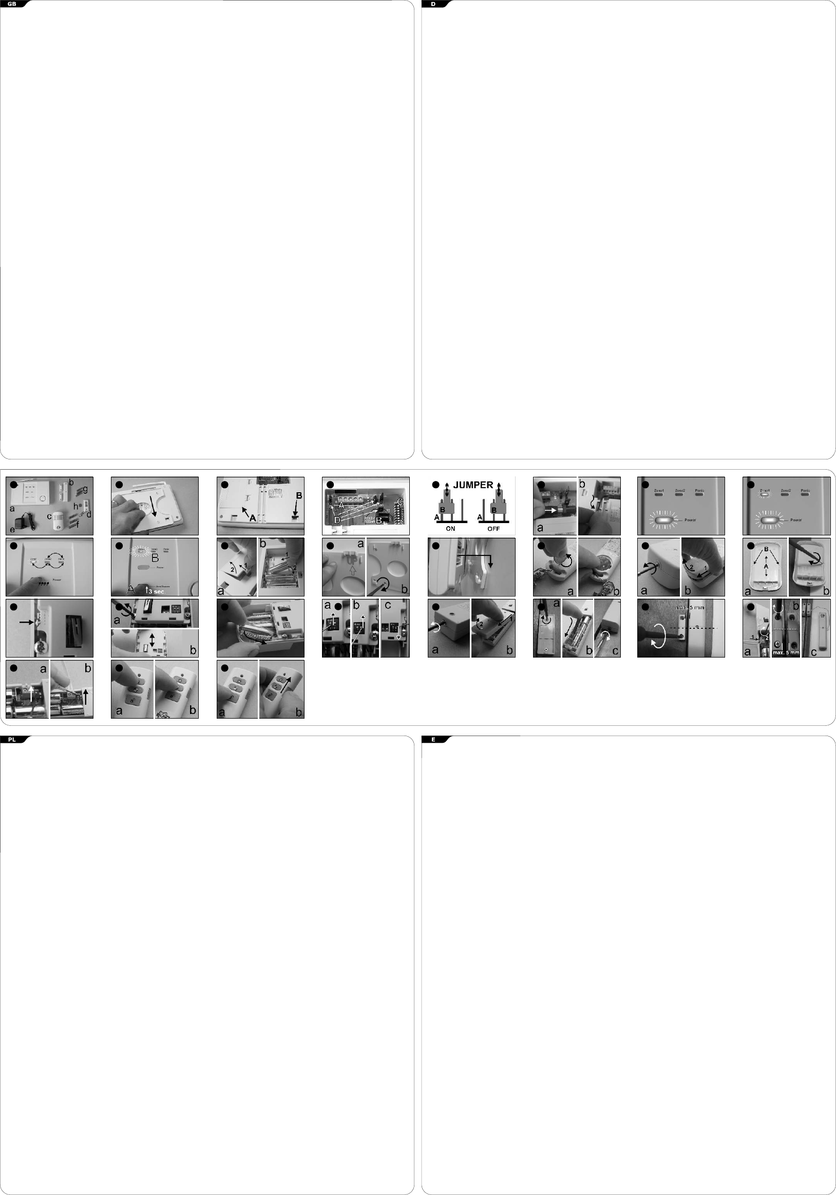
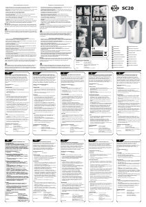
PACKAGE CONTENTS (1)
a. Central unit and control unit (HA63) Switching the central unit back to 24 HOUR POSITION: Wireless exterior wall mount
b. Wireless magnetic contact with external magnet (SA63M) - take the adapter out of the wall socket The central unit has a sender for wireless operation of this exterior wall mount
c. Wireless motion detector (SA63P) - switch jumper 3 back to OFF SA68G.
d. Remote control (SA63R) - plug the adapter back into the socket Install an identical code for both the central unit and exterior wall mount by using
e. Adapter 12 V 500 mA the DIP switches (4c).
After all components have been programmed everything can be installed.
f. 3 x battery LR06 type AA 1, 5 V (for SA63P)
Wireless smoke detector
g. 3 x battery LR03 type AAA 1, 5 V (for SA63M)
Central/control unit HA63 (a)
Additionally, a smoke detector SA68B can be used. Registering is done in the same
h. Lithium button cell battery 3V type CR2032 (for SA63R)
- Make sure the power to the central unit (a) is switched off (remove adapter (e)
manner as with the other components, however just the Emergency LED should be
from wall socket).
PREPARATION turned on at step 1.
- Switch jumper JP3 back to OFF (24 hour position).
Check and pay attention to the following points before installing the central unit (a)
- Open the battery compartment (11a) and insert 6 LR6 type AA 1, 5 V batteries TIPS
and detectors (b, c):
(11b). NOTE!!!! If rechargeable batteries (1, 2 V) are used jumper JP5 must be - Instead of using screws, the detector and magnet of the SA63M can be installed
1. An area with only one entrance door and not fitted with windows can be secured
switched to ON. by using double sided (foam) tape. Please take care not to tape down the tamper
with a magnetic contact (b) on the door (i.e. a garage, a basement or storage
- Attach the mounting plate in the correct position (12a) to a level surface and switch at the back of the detector.
area, or an attic).
mark the screw holes. Drill 4 holes (use plugs if necessary) and install the - A magnetic contact is also perfectly usable for safeguarding cupboards and/or
2. For areas which are only accessible via another central area it is usually sufficient
mounting plate in place (12b). display cabinets.
to safeguard that central area (i.e. a landing) with a motion detector (c).
- Close the battery compartment and slide the central unit (a) onto the mounting - Never place a motion detector directly opposite a window and avoid direct (sun)
3. All open areas with multiple access ways can best be protected with a motion
plate (13). light on the detector screen (also think of mirrors, etc).
detector (c).
- Never place a motion detector directly above a radiator or other heat source. This
4. Place the central unit (a) and the detectors (b, c) preferably at least 0,5 meters
Remote control SA63R (e)
also applies to central heating pipes.
from metal objects like central heating pipes, water pipes and radiators.
This is used to operate the system. The Lithium battery CR2032 (h) provides the
- Avoid installing detectors in places where excessive vibrations might take place.
5. Place the central unit (a) always near a wall socket in order to connect the
power and under normal circumstances battery life is one year. If the battery power
- Bear in mind that the system might be activated by house pets. If this is
adapter (e).
becomes too weak the LED will stay on after a button has been pushed. The battery
unavoidable, try using the next “trick”: install the motion detector UPSIDEDOWN
6. Please realise that the central unit (a) also contains a siren. Naturally it's the
then needs to be replaced.
at approx. 1 meter (depending on the size of the animal) above the floor. This
intention that this siren can be heard everywhere.
- Use a coin to open the battery compartment at the back (14a).
creates an “open walking space” of approx. 60 to 80 cm.
- Place the Lithium battery CR2032 (f) with the + facing up in the battery
PLANNING - A detector will automatically switch into stand-by to save battery power. After
compartment (14b) and close it again.
Before the central unit (a) and detectors (b, c) are installed a careful plan should be making a detection, a detector will not give out a signal for approx. 1 minute.
made about what should be protected and which detector should be used. Remember this when testing; allow a detector time to re-activate.
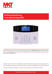
Motion detector SA63P(c)
Also think about which detector should be connected to which zone. Make a map of
This detector guards indoor areas up to 10x10m, sending an alarm signal when
SPECIFICATIONS
the house and on it mark what will be installed where, and which zone that
motion is detected. The detector is powered by 3 LR06 type AA 1,5V batteries (f).
particular detector will be connected to.
- The best placement in the area to be guarded is in a corner at a height of approx. General
* Zone 1 can be switched on separately (selective position).
2 meters. This gives an optimal range and the highest sensitivity. Frequency 868 MHz
* Zone 2 will only be switched on if the entire system is engaged.
- Unscrew the little screw at the bottom (15a) and open the battery compartment Distance 50m
* The emergency zone is always switched on and is meant for panic, fire and
(15b).
tamper alarm.
Control unit
- For placement on a level wall, open the holes marked A. For corner placement
* The selective position can be used, for example, to separately switch on the
Zones 3
(recommended) open the holes marked B (16a).
downstairs floor if you are asleep upstairs.
Adapter 12V 500mA DC
- Next install the cover against the wall (16b).
* A maximum of 10 detectors can be installed in every zone.
Battery power 6x LR06 AA 1,5V (also rechargeable)
- The default installation for range is set at 5 (17). This is approx. 10 meters and
* A maximum of 4 remote controls can be connected to the system.
Tamper proof yes
sufficient for i.e. a living room.
Alarm output 12V/200mA
- If the adjustment screws are loosened (18a) the complete inner construction can
INSTALLATION AND PROGRAMMING
Battery life approx. 48 hours
be moved (18b). Position 3 is a range of approx. 7 meters (bedrooms etc.) and
This can best be done before the central unit (a) and detectors (b, c) are installed in
Replace normal batteries every year
position 1 is a range of approx. 5 meters and meant for smaller areas like a
their definite location. Place all components on a table to follow the procedure.
hallway or landing.
* Insert batteries in all components in the correct manner (this is described for
Remote control
- Tighten the adjustment screws again after adjusting the range.
every specific component).
Battery power 1x CR2032 3V lithium
- Insert the 3 batteries LR06 Type AA 1, 5 V (f) in the correct manner (19).
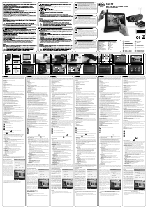
* Remove the mounting plate (2) of the central unit (a) by gently sliding it
Battery life approx.1 year
- Let the detector warm up and adjust for 1 minute.
downwards.
- Set mini-switch 1 to ON (20a), the walk-test position. Set mini-switch 2 to ON
* The battery compartment (3a) and the tamper switch (3b) are now visible.
PIR Detector
(20b), high sensitivity. With every movement the LED behind the detection
* At the top the opening for adjustments and connections can be seen (4). This
Battery power 3x LR06 AA 1,5V
screen will light up immediately.
contains the following elements:
Battery life approx. 1 year
- Set mini-switch 2 to OFF (20c), low sensitivity. The LED behind the detection
- connection interface T1 for adjustments of the external siren and phone dialer
Detection angle 110°
screen will flash twice at every movement. The choice between high and low
(4a).
Detection distance max. 10m
sensitivity strongly depends on the environment in which the detector is placed.
- connection interface JB1 for the power adapter (e) (4b).
Tamper proof yes
Especially temperature and draft are an important factor. If these are constantly
- switch block S3 with DIP switches (4c) to program the code of the wireless
high set the detector to low sensitivity.
outside wall mounted flashing light (SA68G).
Magnetic detector
- AT LEAST SET MINI-SWITCH 1 BACK TO OFF = the normal detection position
- 4 jumpers JP1, JP3, JP4 and JP5 (4d) with the following functions:
Battery power 3x LR03 AAA 1,5V
(otherwise the batteries will drain very quickly).
Battery life approx. 1 year
JP1 ON = External tampering protection connected. - Install the casing onto the installed back plate. Nothing should be flashing or lit
Tamper proof yes
OFF = No external tampering protection connected. up now, even when there is movement.
Default setting is OFF
Wireless magnet contact with external magnet SA63M (b)
JP3 ON = Learning position
This detector is used indoors for doors and windows. There are 2 components, the
OFF = Normal 24 hour position
detector and a magnet. One part is mounted on the window or door frame and the
Default setting is OFF
other is placed on the window or door. As soon as the door or window is opened an
JP4 ON = Alarm duration 10 minutes
alarm signal is set off. Power is supplied by three LR03 type AAA 1, 5 V batteries. A
OFF = Alarm duration 3 minutes
control LED has been built in. If this lights up when activated, the batteries need to
Default setting is OFF
be replaced. For instalment in difficult to reach places or wide window sills it is
JP5 ON = Using rechargeable batteries
possible to use the external contact. This ensures installation in almost every
OFF = Using regular alkaline batteries
situation.
Default setting is OFF
- NEVER install a magnetic contact on the side where the hinges are located.
By default there are NO batteries in the central unit (a). However, we do advise to - Placement at the top is preferred. Left or right-opening doors or windows are not
use batteries so the system will continue to function in case of a power failure. a factor then.
WARNING!! If JP5 is switched to ON please check that rechargeable batteries are - Undo the little screw at the bottom (21a) and open the cover (21b).
used, or there is a real danger of fire or explosion. A jumper is nothing more than a - Install the mounting plate on the frame (22a). Insert the type AAA 1,5V batteries
switch made of three pins (5a) and a connector, which is manually placed over 2 of (g) in the correct manner (22b) and close the detector again (22c).
the 3 pins (5b). This enables ON and OFF switching. - Attach the magnet in such a manner that the line on the detector and the magnet
are evenly matched. The opening can be no more than 5 mm (23).
- Connect the adapter (e) to JB1 (6a) and feed the wire down through the slots
- If the external contact is used, it first needs to be connected to the detector by
(6b).
using the cable connector in the detector (24a).
- Plug the adapter (e) into a wall socket. A beep will sound and the power LED at
- The external contact is then installed on the frame opposite the magnet (24b).
the front of the central unit (a) should light up (7). This is the 24 HOUR
- The control LED should not be on now.
POSITION and indicates the system is functioning.
- Adjusting the SA63M depends on using the external contact. If this is not used
(normal situation), mini-switch 1 should be set to ON (25a) and 2 to OFF.
The next step is to program the different components into the central unit.
- When using the external contact, mini-switch 1 should be set to OFF and mini-
For this the system needs to be switched to the LEARN MODE. The procedure is as
switch 2 to ON (25b).
follows:
- Now open the window or door. The control LED should turn on.
- Take the adapter (e) out of the wall socket and remove the batteries from the
central unit (a) if necessary.
OPERATION
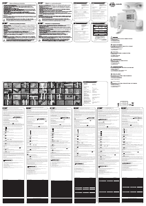
- Set jumper JP3 to ON. This is the learn position. Plug the adapter (e) back into
The system can be exclusively operated by using the remote control (d).
the wall socket.
- When pressing the buttons the LED should light up.
- A beep will sound and the power LED at the front is on again, together with the
- Complete activation of the system is done by pressing the upper control switch
zone 1 LED (8).
(26a). This will switch on all zones simultaneously. At activation a 15 second beep
will be heard. This is the delay time during which you can leave the premises
Follow the next steps to register a remote control:
without setting off the alarm.
1- Use the POWER button to switch on the correct zone(s). With a remote control it
Switching off the system is done by pressing the bottom control switch (27a).
always is zone 1 and 2 together.
Make sure to do this before entering the premises.
2- Press the ARM/DISARM button of the central unit (a) for 3 seconds (10a).
- Partial activation is done by pressing the middle control switch (26b). This will
You will hear 3 short beeps followed by 1 long beep. The LEDs of the selected
only activate the detectors which are connected to Zone 1. In this mode the
zone will start flashing (10b).
central unit will not emit a beep, the zone is immediately activated.
3- You now have 30 sec to “teach” the central unit (a) the ID-code. A beep will
- Switching off the system is done by pressing the bottom control switch (27a).
sound every 3 sec.
Note, now the system will emit a beep if this zone is activated before the system
4- Press a random button on the remote control (d).
is switched off.
5- When the central unit (a) recognises the remote control a long beep will follow,
- At the side there is a so-called panic button (slide) (27b). If this is slid upward
after which other components can be registered.
the system is immediately activated, even if the system is set in 24 hour mode.
- After the alarm one of the zone LEDs stays on. It indicates where the alarm was
Registering the different components is done by the same procedure as described
set off, and after re-activation this LED will turn off again.
above, but at step 1 now only one zone (1, 2 or Emergency) should be switched on
with the POWER button. At step 4 the tamper switch must be depressed and
ACCESSORIES
released. Repeat the registering procedure until all components are installed. If a
Up to 10 magnetic contacts or motion detectors can programmed into both zone 1
detector must be registered with a different group, it can simply be re-registered
and 2. Also 4 remote controls can be installed.
with that group.
HA63S DRAHTLOSE 3-ZONEN-ALARMANLAGE 5- Wenn das Zentraleinheit (a) die Fernbedienung erkennt, folgt ein langer Piepton, BETRIEB
nach dem andere Komponenten angemeldet werden können. Die Anlage kann nur mit Fernbedienung (d) gesteuert werden.
- Beim Drücken von Tasten sollte die LED aufleuchten.
Die HA63S ist ein einfaches drahtloses Sicherheitssystem für Häuser und
- Die komplette Aktivierung der Anlage wird durch Drücken des oberen
Wohnungen. Das System ist gegen unerlaubte Eingriffe geschützt. Es wird Die Anmeldung der verschiedenen Komponenten wird mit denselben Schritten, wie
Kontrollschalters vorgenommen (26a). Dies schaltet alle Zonen gleichzeitig ein. Bei
über eine Fernbedienung gesteuert. Zusätzliches Zubehör, z.B. ein oben beschrieben, vorgenommen, aber bei Schritt 1 sollte jetzt nur eine Zone (1, 2
der Aktivierung ist ein 15 Sekunden langer Piepton zu hören. Dies ist die
Telefonwähler, ein drahtloses, codiertes Türschloss, Rauchmelder oder oder Notfall) mit der Taste POWER angeschaltet werden. Bei Schritt 4 muss der
Verzögerungszeit, in der Sie das Haus ohne Auslösen des Alarms verlassen können.
Außenwandhalter können angeschlossen werden. Der Anschluss zusätzlicher Eingriffschalter gedrückt und losgelassen werden. Wiederholen Sie den
Das Ausschalten der Anlage wird durch Drücken des unteren Kontrollschalters
Detektoren und Fernbedienungen ist auch möglich (SA68P, SA68M, SA68R). Anmeldevorgang bis alle Komponenten installiert sind. Wenn ein Detektor bei einer
vorgenommen (27a). Beachten Sie, dass Sie dies vor Betreten des Hauses
anderen Gruppe angemeldet werden muss, kann er einfach neu bei dieser Gruppe
durchführen müssen.
angemeldet werden.
PACKUNGSINHALT (1)
- Die teilweise Aktivierung der Anlage wird durch Drücken des mittleren
a. Zentral- und Steuereinheit (HA63)
Kontrollschalters vorgenommen (26b). Dies aktiviert nur die Detektoren, die mit
b. Drahtloser Magnetkontakt mit externem Magneten (SA63M) Zurücksetzen der Zentraleinheit
Zone 1 verbunden sind. In diesem Modus gibt die Zentraleinheit keinen Piepton ab,
c. Drahtloser Bewegungsmelder (SA63P) Die Rücksetzung der Anlage wird von Zone zu Zone auf folgende Art vorgenommen:
die Zone wird sofort aktiviert.
d. Fernbedienung (SA63R) - schalten Sie die Zentraleinheit in den LEARN MODE/Lernmodus, wie oben
- Das Ausschalten der Anlage wird durch Drücken des unteren Kontrollschalters
e. Netzadapter 12 V 500 mA beschrieben
vorgenommen (27a). Beachten Sie, dass die Anlage eine Piepton abgibt, wenn diese
f. 3 x Batterie LR06 Typ AA 1, 5 V (für SA63P) - verwenden Sie die Taste POWER, um die Zone auszuwählen, die zurückgesetzt
Zone aktiviert ist, bevor die Anlage ausgeschaltet wird.
g. 3 x Batterie LR03 Typ AAA 1, 5 V (für SA63M) werden muss
- Auf der Seite befindet sich ein so genannter Panik-Knopf (schieben) (27b). Wenn
h. Lithium-Knopfzellenbatterie 3V Typ CR2032 (für SA63R) - drücken Sie 3 Sekunden lang auf ARM/DISARM, dann drücken Sie diese Taste
dieser nach oben geschoben wird, wird die Anlage sofort aktiviert, auch wenn die
erneut 6 Sekunden lang
Anlage auf den 24-Stunden-Modus eingestellt ist.
Die ausgewählte Zone wurde jetzt zurückgesetzt.
VORBEREITUNG
- Nach dem Alarm leuchtet eine der Zonen-LEDs weiter. Dies zeigt an, wo ein Alarm
Beachten Sie die folgenden Punkte, bevor Sie das Zentraleinheit (a) und die Detektoren
ausgelöst wurde und nach der Wiederaktivierung geht diese LED aus.
(b, c) installieren: Zurückschalten der Zentraleinheit auf die 24 HOUR POSITION/24-Stunden-Stellung:
1. Ein Bereich mit nur einem Eingang und ohne Fenster kann mit einem Magnetkontakt - ziehen Sie den Stecker des Netzadapter aus der Netzsteckdose
ZUBEHÖR
(b) an der Tür (z.B. Garage, Keller, Lagerraum oder Dachboden) gesichert werden. - setzen Sie den Jumper 3 zurück auf OFF
Bis zu 10 Magnetkontakte oder Bewegungsmelder können in beiden Zonen 1 und 2
2. In Bereichen, die nur über einen anderen zentralen Bereich zugänglich sind, ist - schließen Sie den Netzadapter wieder an die Netzsteckdose an
programmiert werden. Es können auch 4 Fernbedienungen installiert werden.
normalerweise eine Sicherung dieses zentralen Bereichs (z.B. Treppenabsatz) mit
einem Bewegungsmelder (c) ausreichend.
Nach der Programmierung aller Komponenten kann alles installiert werden.
Drahtloses codiertes Türschloss
3. Alle offenen Bereiche mit mehreren Zugangswegen können am besten mit einem
Ein drahtloses codiertes Türschloss SA68C kann auch mit der Anlage verwendet
Bewegungsmelder (c) geschützt werden.
Zentral/Steuereinheit HA63 (a)
werden. Die Anmeldung wird auf die gleiche Weise wie die der anderen Komponenten
4. Plazieren Sie das Zentraleinheit (a) und die Detektoren (b, c) vorzugsweise in einem
- Stellen Sie sicher, dass der Strom der Zentraleinheit (a) ausgeschaltet ist (ziehen Sie
durchgeführt, aber beim Programmschritt 1 sollten die LEDs der Zonen 2 und Notfall
Abstand von mindestens 0,5 Meter von metallischen Objekten, z.B.
den Adapter(e) aus der Netzsteckdose).
aufleuchten.
Zentralheizungsrohen, Wasserleitungen und Radiatoren.
- Setzen Sie den Jumper JP3 zurück auf OFF (24-Stunden-Stellung).
5. Plazieren Sie die Zentraleinheit (a) immer in der Nähe einer Steckdose für den
- Öffnen Sie das Batteriefach (11a) und setzen Sie 6 LR6 Typ AA 1,5 V Batterien ein
Zusätzliche Sirene oder Blinklicht
Netzadapteranschluss (e).
(11b). ACHTUNG!!!! Wenn wiederaufladbare Akkus verwendet werden (1,2 V), muss
Der Anschlussblock kann auch für den Anschluss einer 12V-Sirene oder eines Blinklichts
6. Bitte beachten Sie, dass das Zentraleinheit (a) auch eine Sirene enthält. Diese
der Jumper JP5 auf ON gewechselt werden.
verwendet werden. Schließen Sie diese an P+ und V- an, max. Stromaufnahme
Sirene sollte überall zu hören sein.
- Bringen Sie die Montageplatte in der richtigen Position (12a) auf einer ebenen
200mA.
Oberfläche an und markieren Sie die Löcher für die Schrauben. Bohren Sie 4 Löcher
PLANUNG
(verwenden Sie, falls nötig, Dübel) und befestigen Sie die Montageplatte daran
Drahtloser Außenwandhalter
Vor der Installation der Zentraleinheit (a) und der Detektoren (b, c) sollte ein genauer
(12b).
Die Zentraleinheit hat einen Sender für den drahtlosen Betrieb dieses
Plan erstellt werden, was zu schützen ist und welcher Detektor verwendet werden
- Schließen Sie das Batteriefach und schieben Sie die Zentraleinheit (a) auf die
Außenwandhalters SA68G.
sollte.
Montageplatte (13).
Setzen Sie einen identischen Code für Zentraleinheit und den Außenwandhalter mittels
Planen Sie auch, welcher Detektor mit welcher Zone verbunden werden sollte. Erstellen
der DIP-Schalter (4c).
Sie eine Karte des Hauses und markieren Sie darauf, was an welcher Stelle installiert
Fernbedienung SA63R (e)
wird und mit welcher Zone der spezielle Detektor verbunden wird.
Diese wird zur Bedienung der Anlage verwendet. Die Lithium-Batterie CR2032 (h)
* Zone 1 kann separat angeschaltet werden (selektive Position). Drahtloser Rauchmelder
liefert die Energie und unter normalen Umständen beträgt die Batterielebensdauer 1
* Zone 2 wird nur angeschaltet, wenn die gesamte Anlage eingeschaltet ist. Zusätzlich kann ein Rauchmelder SA68B verwendet werden. Die Anmeldung wird auf
Jahr. Wenn die Batterieleistung schwach wird, leuchtet die LED weiter, nachdem eine
* Die Notfall-Zone ist immer eingeschaltet und ist für Panik, Feuer- und Eingriffsalarm die gleiche Weise wie die der anderen Komponenten durchgeführt, aber beim
Taste gedrückt wurde. Dann muss die Batterie ausgetauscht werden.
gedacht. Programmschritt 1 sollte nur die LED der Zone Notfall aufleuchten.
- Verwenden Sie eine Münze, um das Batteriefach auf der Rückseite zu öffnen (14a).
* Die selektive Position kann zum Beispiel verwendet werden, um das untere
- Setzen Sie die Lithium-Batterie CR2032 (f) mit dem + nach oben in das Batteriefach
Stockwerk separat anzuschalten, wenn Sie im oberen Stockwerk schlafen.
TIPPS
(14b) ein und schließen Sie es wieder.
* Maximal 10 Detektoren können in jeder Zone installiert werden.
- Anstelle von Schrauben kann der Detektor und der Magnet des SA63M auch mit
* Maximal 4 Fernbedienungen können an die Anlage anschlossen werden.
einem doppelseitigen Klebeband (Schaum) befestigt werden. Achten Sie bitte
Bewegungsmelder SA63P (c)
darauf, dass der Eingriffschalter auf der Rückseite nicht verklebt wird.
Dieser Detektor schützt Innenbereiche von bis zu 10m x 10 m und sendet ein
INSTALLATION UND PROGRAMMIERUNG
- Ein Magnetkontakt kann auch für die Sicherung von Schränken und/oder
Alarmsignal, wenn eine Bewegung erkannt wird. Der Detektor wird von 3 LR06 Typ AA
Diese kann am besten durchgeführt werden, bevor das Zentraleinheit (a) und die
Schauvitrinen verwendet werden.
1,5 V Batterien (f) versorgt.
Detektoren (b, c) an den endgültigen Standorten installiert sind. Legen Sie alle
- Bringen Sie einen Bewegungsmelder niemals direkt gegenüber einem Fenster an
- Die beste Position in dem zu überwachenden Bereich ist in einer Ecke auf einer Höhe
Komponenten auf einem Tisch aus, um das Folgende durchzuführen.
und vermeiden Sie direktes (Sonnen-) Licht auf dem Detektorschirm (beachten Sie
von ca. 2 Metern. Dies erlaubt einen optimalen Erkennungsbereich und die höchste
* Setzen Sie die Batterien in alle Komponenten richtig ein (dies wird für jede
dabei auch Spiegel u.a.)
Empfindlichkeit.
spezifische Komponente beschrieben).
- Bringen Sie einen Bewegungsmelder niemals direkt über einem Heizradiator oder
- Lösen Sie die kleine Schraube auf der Unterseite (15a) und öffnen Sie das
* Entfernen Sie die Montageplatte (2) der Zentraleinheit (a), indem Sie sie vorsichtig
einer anderen Wärmequelle an. Dies gilt auch für Heizungsrohre.
Batteriefach (15b).
nach unten schieben.
- Vermeiden Sie die Installation von Detektoren an Stellen, an denen starke
- Für die Montage auf einer ebenen Wand öffnen Sie die mit A markierten Löcher. Für
* Das Batteriefach (3a) und der Eingriffsschalter (3b) sind jetzt sichtbar.
Erschütterungen auftreten können.
die Montage in einer Ecke (empfohlen), öffnen Sie die mit B markierten Löcher
* Im oberen Teil ist die Öffnung für Einstellungen und Anschlüsse zu sehen (4). Diese
- Beachten Sie, dass die Anlage von Haustieren aktiviert werden kann. Wenn dies
(16a).
enthält die folgenden Elemente:
nicht zu vermeiden ist, versuchen Sie den folgenden „Trick“: installieren Sie den
- Als nächstes installieren Sie die Abdeckung zur Wand (16b).
- Anschluss-Interface T1 für Einstellungen der externen Sirene und Telefonwähler
Bewegungsmelder UMGEKEHRT auf ca. 1 Meter Höhe (abhängig von der Größe des
- Werkseitig ist ein Erkennungsbereich von 5 voreingestellt (17).Dies sind ca. 10
(4a).
Tiers) über dem Boden. Dies schafft einen „offenen Gehbereich“ von ca. 60 - 80cm.
Meter und ist z.B. für ein Wohnzimmer ausreichend.
- Anschluss-Interface JB1 für den Netzadapter (e) (4b).
- Ein Detektor schaltet automatisch in Stand-by, um Batterieleistung zu sparen. Nach
- Wenn die Einstellschrauben gelöst sind (18a), kann die gesamte innere Konstruktion
- Schalterblock S3 mit DIP-Schaltern (4c), um den Code des an der Außenwand
einer Erkennung gibt ein Detektor ca. 1 Minute lang kein Signal ab. Beachten Sie
bewegt werden (18b). Position 3 ist ein Erkennungsbereicht von ca. 7 Metern
montierten drahtlosen Blinklichts (SA68G) zu programmieren.
dies beim Testen; lassen Sie dem Detektor Zeit zur Reaktivierung.
(Schlafzimmer u.a.) und Position 1 ist ein Erkennungsbereich von ca. 5 Metern und
- 4 Jumper JP1, JP3, JP4 und JP5 (4d) mit den folgenden Funktionen:
ist für kleinere Bereiche, z.B. Flur oder Treppenabsatz gedacht.
TECHNISCHE DATEN
- Ziehen Sie die Einstellschrauben wieder nach der Einstellung des
JP1 ON = Externe Eingriffssicherung angeschlossen.
Erkennungsbereichs an.
OFF = Keine externe Eingriffssicherung angeschlossen.
- Setzen Sie die 3 Batterien LR06 Typ AA 1,5 V (f) richtig ein (19). Allgemein
Die Voreinstellung ist OFF.
- Lassen Sie den Detektor sich 1 Minute lang aufwärmen und anpassen. Frequenz 868 MHz
JP3 ON = Einlernstellung
- Setzen Sie den Mini-Schalter 1 auf ON (20a), die Gehtest-Stellung. Setzen Sie den Abstand 50m
OFF = Normale 24-Stunden-Stellung
Mini-Schalter 2 auf ON (20b), hohe Empfindlichkeit. Bei jeder Bewegung leuchtet
Die Voreinstellung ist OFF.
sofort die LED hinter der Detektorscheibe auf.
Steuereinheit
JP4 ON = Alarmdauer 10 Minuten
- Setzen Sie den Mini-Schalter 2 auf OFF (20c), niedrige Empfindlichkeit. Die LED
Zonen 3
OFF = Alarmdauer 3 Minuten
hinter der Detektorscheibe blinkt bei jeder Bewegung zwei Mal auf. Die Wahl
Netzadapter 12V 500mA DC
Die Voreinstellung ist OFF.
zwischen hoher und niedriger Empfindlichkeit ist stark von der Umgebung abhängig,
Batterieversorgung 6x LR06 AA Batterien 1,5 V (auch wiederaufladbar)
JP5 ON = Verwendung von wiederaufladbaren Akkus
in welcher der Detektor installiert wird. Besonders Temperatur und Zugluft sind
Gegen Eingriffe geschützt ja
OFF = Verwendung von normalen Alkalien-Batterien
wichtige Faktoren. Wenn diese konstant hoch sind, stellen Sie den Detektor auf eine
Alarm-Ausgang 12V/200mA
Die Voreinstellung ist OFF.
niedrige Empfindlichkeit ein.
Batterielebensdauer ca. 48 Stunden
- SETZEN SIE MINDESTENS MINI-SCHALTER 1 ZURÜCK AUF OFF = die normale
Ersetzen Sie normale Batterien nach einem Jahr
Werksseitig befinden sich KEINE Batterien im Zentraleinheit (a). Wir empfehlen jedoch,
Erkennungsstellung (sonst leeren sich die Batterien sehr schnell).
Batterien zu verwenden, damit die Anlage auch bei Stromausfall weiter funktioniert.
- Installieren Sie das Gehäuse auf der montierten Rückplatte. Jetzt sollte nichts
Fernbedienung
WARNUNG!! Wenn JP5 auf ON geschaltet ist, überprüfen Sie bitte, ob wiederaufladbare
blinken oder aufleuchten, auch wenn es Bewegungen gibt.
Batterieversorgung 1x CR2032 3V Lithium
Akkus verwendet werden. Falls nicht, besteht dringende Feuer- oder Explosionsgefahr.
Batterielebensdauer ca. 1 Jahr
Ein Jumper ist nur ein Schalter, der aus drei Pins (5a) und einem Stecker besteht, der
Drahtloser Magnetkontakt mit externem Magneten SA63M (b)
manuell über 2 der 3 Pins gesteckt wird (5b). Dies ermöglicht ein ON/Ein- und
Dieser Detektor wird in Innenbereichen für Türen und Fenster verwendet. Er besteht
PIR-Detektor
OFF/Ausschalten.
aus 2 Teilen, dem Detektor und einem Magneten. Ein Teil wird auf dem Fenster oder
Batterieversorgung 3x LR06 AA 1,5V
dem Türrahmen montiert und der andere auf dem Fenster oder der Tür. Sobald die Tür
Batterielebensdauer ca. 1 Jahr
- Verbinden Sie den Netzadapter(e) mit JB1 (6a) und führen Sie das Kabel durch die
oder das Fenster geöffnet wird, wird ein Alarmsignal gesendet. Die Stromversorgung
Erkennungswinkel 110°
Schlitze (6b).
stellen drei LR03 AAA 1,5 V Batterien sicher. Eine Kontroll-LED ist eingebaut. Wenn
Erkennungsabstand max. 10m
- Schließen Sie den Netzadapter (e) an eine Netzsteckdose an. Ein Piepton ist zu
diese aufleuchtet, wenn der Kontakt aktiviert ist, müssen die Batterien ausgetauscht
Gegen Eingriffe geschützt ja
hören und die Betriebs-LED auf der Vorderseite der Zentraleinheit (a) sollte leuchten
werden. Für die Installation an schlecht zugänglichen Stellen oder bei breiten
(7).Dies ist die 24 HOUR POSITION /24-STUNDEN-STELLUNG und zeigt an, dass die
Fensterbrettern ist die Verwendung eines externen Kontakts möglich. Dies ermöglicht
Magnet-Detektor
Anlage funktioniert.
die Installation in fast allen Umgebungen.
Batterieversorgung 3x LR03 AAA 1,5V
- Installieren Sie NIEMALS einen Magnetkontakt auf der Scharnierseite.
Batterielebensdauer ca. 1 Jahr
Der nächste Schritt ist die Programmierung der verschiedenen Komponenten in der - Vorzugsweise ist er an der Oberseite zu installieren. Der Links- oder Rechtsanschlag
Gegen Eingriffe geschützt ja
Zentraleinheit. von Türen oder Fenster ist dann nicht zu beachten.
Dafür muss die Anlage in den LEARN MODE/Lernmodus geschaltet werden. Der Ablauf - Lösen Sie die kleine Schraube auf der Unterseite (21a) und öffnen Sie die
ist folgender: Abdeckung (21b).
- Ziehen Sie den Stecker des Adapters (e) aus der Steckdose und entnehmen Sie die - Installieren Sie die Montageplatte am Rahmen (22a). Setzen Sie die Typ AAA 1,5 V
Batterien aus dem Zentraleinheit (a), falls nötig. Batterien (g) richtig ein (22b) und schließen Sie den Detektor wieder (22c).
- Setzen Sie den Jumper JP3 auf ON. Dies ist die Einlernstellung. Schließen Sie den - Befestigen Sie den Magneten so, dass die Linie auf dem Detektor und die auf dem
Netzadapter (e) wieder an die Netzsteckdose an. Magneten übereinstimmen. Die Öffnung darf nicht mehr als 5 mm betragen (23).
- Ein Piepton ist zu hören und die Betriebs-LED auf der Vorderseite leuchtet wieder, - Wenn der externe Kontakt verwendet wird, muss er zuerst mit dem Detektor über
zusammen mit der LED Zone 1 (8). den Kabelstecker im Detektor verbunden werden (24a).
- Der externe Kontakt wird dann auf dem Rahmen gegenüber dem Magneten
installiert (24b).
Folgen Sie den nächsten Schritten, um eine Fernbedienung anzumelden:
- Die Kontroll-LED sollte nun leuchten.
1- Verwenden Sie die Taste POWER, um die korrekte/n Zone/n einzuschalten. Bei einer
- Die Einstellung des SA63M ist abhängig von der Verwendung des externen Kontakts.
Fernbedienung sind es immer die Zonen 1 und 2 zusammen.
Wenn dieser nicht verwendet wird (normale Situation), sollte der Mini-Schalter 1 auf
2- Drücken Sie auf dem Zentraleinheit (a) 3 Sekunden lang auf ARM/DISARM (10a).
ON und 2 auf OFF gestellt werden (25a).
Es sind 3 kurze Pieptöne, gefolgt von 1 langen Piepton zu hören. Die LEDs der
- Wenn der externe Kontakt verwendet wird, sollte der Mini-Schalter 1 auf OFF und
ausgewählten Zone beginnen zu blinken (10b).
der Mini-Schalter 2 auf ON (25b) gesetzt werden.
3- Jetzt haben Sie 30 Sek, um dem Zentraleinheit (a) den ID-Code zu „lehren“. Ein
- Öffnen Sie jetzt das Fenster oder die Tür. Die Kontroll-LED sollte nun leuchten.
Piepton ist alle 3 Sekunden zu hören.
4- Drücken Sie auf irgendeine Taste auf der Fernbedienung (d).
SISTEMA DE ALARMA DE 3 ZONAS después del cual se podrán registrar otros componentes. cual podrá abandonar la estancia sin desconectar la alarma.
INALÁMBRICO HA63S La desconexión de sistema se realiza al pulsar el interruptor de control inferior
(27a). Asegúrese de hacer esto antes de acceder a la estancia.
La programación de los diferentes componentes se realiza siguiendo el mismo
- La activación parcial se realiza al pulsar el interruptor de control central (26b).
El HA63S es un simple sistema de seguridad para casas y apartamentos. procedimiento que se describe más arriba, pero en este caso en el paso 1 sólo una
Este sólo activará los detectores que están conectados a la zona 1. En este modo
Este sistema a prueba de manipulación se utiliza mediante un mando a zona (1, 2 o Emergencia) mediante el botón POWER. En el paso 4 deberá pulsar y
la unidad central no emitirá ningún bip. La zona se activa inmediatamente.
distancia. Se pueden conectar accesorios extra, como un marcador liberar el interruptor de alarma. Repita el procedimiento de registro hasta que todos
- La desactivación del sistema se realiza al pulsar el interruptor de control inferior
telefónico, una cerradura codificada inalámbrica, un detector de humos o los componentes estén instalados. En caso de tener que registrar un detector con un
(27a). Atención, ahora el sistema emitirá un bip si esta zona se active antes de
un soporte exterior. También es posible conectar detectores y controles grupo diferente, podrá ser simplemente registrado de nuevo con ese grupo.
que el sistema de desactive.
remotos extra (SA68P, SA68M, SA68R).
- A un lado, hay el llamado botón de pánico (deslizar) (27b). Si se desliza hacia
Reajuste de la unidad central
arriba, el sistema se active inmediatamente, aunque el sistema se ajuste en el
CONTINIDOS DEL EMBALAJE (1) El reajuste del sistema se realiza zona a zona de la manera siguiente:
modo 24 horas.
a. Unidad central y unidad de control (HA63) - cambie la unidad central al modo LEARN MODE como se describe anteriormente,
- Cuando la alarma se activa en alguna zona, el indicador luminoso LED sigue
b. Contacto magnético inalámbrico con imán externo (SA63M) - utilice el botón POWER para seleccionar la zona que necesita reajustar,
encendido, para indicar donde en qué punto se disparó. Tras la reactivación el
c. Detector de movimiento inalámbrico (SA63P) - pulse el botón ARM/DISARM durante 3 segundos, y a continuación pulse de
indicador luminoso LED se apagará de nuevo.
d. Mando a distancia (SA63R) nuevo este mismo botón durante 6 segundos.
e. Adaptador 12 V 500 mA La zona seleccionada ya ha sido reajustada.
ACCESSORIOS
f. 3 x baterías LR06 tipo AA 1,5 V (para SA63P)
Hasta 10 contactos magnéticos o detectores de movimiento pueden se programados
g. 3 x baterías LR03 tipo AAA 1,5 V (para SA63M)
Conexión de la unidad central de vuelta a la posición 24 HOUR POSITION:
en la zona 1 y en la 2. También se pueden instalar 4 mandos a distancia.
h. Batería de botón de litio CR2032 de 3V (para SA63R)
- desconecte el adaptador de la toma de corriente
- cambie el puente 3 de vuelta a OFF
Cerradura codificada inalámbrica
PREPARACIÓN - conecte de nuevo el adaptador a la toma de corriente
Una cerradura codificada inalámbrica SA68C puede ser utilizada con este sistema.
Compruebe y verifique los siguientes puntos antes de instalar la unidad central (a) y
Su registro se realiza de la misma forma que con los otros componentes, pero al
los detectores (b, c):
Una vez se hayan programado todos los componentes ya se puede instalar todo.
programar el paso 1 los indicadores luminosos LED de la zona 2 y los de emergencia
1. Un área con una sola puerta de entrada que no esté provista de ventanas podrá
deberían encenderse.
ser asegurada con un contacto magnético (b) en la puerta (i.e. un garaje, un
Unidad central/de control HA63 (a)
sótano o un almacén, o un ático).
- Verifique que la alimentación de la unidad central (a) esté desconectada
2. Para áreas que sólo son accesibles a través de otro área central, normalmente es Luz intermitente o sirena extra
(desconecte el adaptador (e) de la toma de corriente).
suficiente con proteger este área central (i.e. un rellano) con un detector de El bloque de terminales también se puede utilizar para conectar una sirena de 12V o
- Cambie el puente JP3 de nuevo a OFF (posición 24 horas).
movimiento (c). una luz parpadeante. Conéctelo a la conexión P+ y V-, voltaje máximo 200mA.
- Abra el compartimiento para baterías (11a) e introduzca 6 baterías LR6 AA de
3. Todas las áreas abiertas con varias vías de acceso pueden estar mejor protegidas
1,5 V (11b). ¡¡¡NOTA!!!! En caso de utilizar baterías recargables (1,2 V), el
con un detector de movimiento (c).
Soporte exterior inalámbrico
puente JP5 deberá cambiarse a ON.
4. Coloque la unidad central (a) y los detectores (b, c) preferentemente a un
La unidad central dispone de un emisor para la función inalámbrica de este soporte
- Coloque la placa de montaje en la posición correcta (12a) sobre una superficie
mínimo de 0,5 metros de objetos metálicos como tuberías de la calefacción,
inalámbrico SA68G.
plana y marque los agujeros donde irán los tornillos. Haga 4 agujeros (utilice
tuberías del agua y radiadores.
Instale el mismo código para la unidad central y el soporte exterior mediante los
tacos si es necesario) e instale la placa de montaje en su lugar (12b).
5. Coloque la unidad central (a) siempre cerca de una toma de corriente para poder
interruptores DIP (4c).
- Cierre el compartimiento para baterías y deslice la unidad central (a) sobre la
conectar el adaptador (e).
placa de sujeción (13).
6. Tenga en cuenta que la unidad central (a) también contiene una sirena.
Detector de humo inalámbrico
Evidentemente, la intención es que se oiga por todas partes.
Adicionalmente, se puede utilizar un detector de humo SA68B. El registro se realiza
Mando a distancia SA63R (e)
de la misma forma que con el resto de los componentes, aunque hay que activar el
Se utiliza para hacer funcionar el sistema. La batería de litio CR2032 (h) ofrece la
PLANIFICACIÓN
indicador luminoso de emergencia en el paso 1.
alimentación y en condiciones normales su vida es de un año. Cuando la potencia de
Antes de instalar la unidad central (a) y los detectores (b, c) se debería elaborar un
la batería sea demasiado baja el indicador luminoso LED se mantendrá encendida
plan cuidadoso sobre qué proteger y qué detector debería ser utilizado.
des de que se haya pulsado un botón. La batería entonces deberá ser reemplazada. CONSEJOS
También deberá tener en cuenta qué detector debería conectarse a qué zona. Dibuje
- Utilice una moneda para abrir el compartimiento para baterías de la parte - En vez de utilizar tornillos, el detector y el imán del SA63M puede ser instalado
un mapa de la casa y marque en él qué instalará, dónde, y en qué zona colocará un
posterior (14a). mediante cinta adhesiva de doble cara. Asegúrese de no pegar el interruptor de
detector en particular.
- Coloque la batería de litio CR2032 (f) en el compartimiento para baterías con el alarma de la parte posterior del detector.
* La zona 1 puede activarse independientemente (posición selectiva).
lado + hacia arriba (14b) y ciérrelo de nuevo. - También se puede utilizar un contacto magnético para proteger armarios y/o
* La zona 2 sólo se activará en caso de que todo el sistema esté ocupado.
vitrinas.
* La zona de emergencia siempre está activa y está pensada para alarma de
- Nunca coloque un detector de movimiento directamente opuesto a una ventana y
Detección de movimiento SA63P(c)
pánico, fuego o movimiento.
evite el contacto de la luz directa (del sol) con la pantalla del detector (piense
Este detector protege áreas interiores de hasta 10x10 m, y envía una señal de
* La posición selectiva puede ser utilizada para, por ejemplo, activar
también en espejos, etc.).
alarma cuando detecta movimiento. El detector se alimenta con 3 baterías LR06 AA
independientemente el piso de abajo si está durmiendo en el de arriba.
- Nunca coloque un detector de movimiento directamente sobre un radiador o una
de 1,5V (f).
* Se pueden instalar un máximo de 10 detectores en cada zona.
fuente de calor, lo que también se aplica a tuberías de la calefacción.
- El mejor emplazamiento en el área que hay que proteger es en un rincón a una
* Se pueden conectar un máximo de 4 mandos a distancia.
- Evite la instalación de detectores en lugares con expuestos a vibraciones
altura aproximada de 2 metros. Así se obtiene un rango óptimo y la mayor
excesivas.
sensibilidad.
INSTALACIÓN Y PROGRAMACIÓN
- Tenga en cuenta que el sistema podría ser activado por un animal doméstico. Si
- Afloje el tornillo pequeño de la parte inferior (15a) y abra el compartimiento para
Antes de que la unidad central (a) y los detectores (b, c) sean instalados en su
le resulta inevitable que esto suceda, pruebe de utilizar el “truco” siguiente:
baterías (15b).
posición definida es mejor seguir los pasos siguientes. Coloque todos los
instale el detector de movimiento bocabajo a aproximadamente 1 metro (según
- Para su colocación en una pared plana, abra los agujeros marcados A. Para la
componentes sobre una mesa para seguir el procedimiento.
el tamaño del animal) del suelo, lo que crea un “paso abierto” de 60 a 80 cm
colocación en una esquina (recomendada) abra los agujeros marcados B (16a).
* Introduzca las baterías en todos los componentes en el sentido correcto (como se
aproximadamente.
- A continuación, instale la cubierta contra la pared (16b).
describe para cada uno de los componentes).
- Un detector cambiará a modo de espera automáticamente para ahorrar batería.
- La instalación predeterminada para obtener alcance se establece en 5 (17). Es de
* Retire la placa de montaje (2) de la unidad central (a) deslizándola hacia abajo.
Después de realizar una detección, un detector no dará señal durante
aproximadamente 10 metros y es suficiente para, por ejemplo, un comedor.
* Podrá ver el compartimiento para baterías (3a) y el interruptor de alarma (3b).
aproximadamente 1 minuto. Recuérdelo en el momento de pruebas; déle tiempo
- Si los tornillos de ajuste se aflojan (18a), se puede mover la construcción interior
* En la parte superior, podrá ver la apertura para ajustes y conexiones (4), que
al detector para su reactivación.
completa (18b). La posición 3 corresponde a un rango de aproximadamente 7
contiene los elementos siguientes:
metros (habitaciones, etc.) y la posición 1 comprende un rango de
- interficie de conexión T1 para ajustes de la sirena externa y el marcador
aproximadamente 5 metros y está pensada para áreas más pequeñas como un ESPECIFICACIONES
telefónico (4a).
vestíbulo o un rellano.
- interficie de conexión JB1 para el adaptador de corriente (e) (4b).
- Apriete de nuevo los tornillos una vez haya ajustado el rango.
General
- bloque de contactos S3 con interruptores DIP (4c) para programar el código de
- Introduzca las 3 baterías LR06 AA de 1,5 V (f) en la posición correcta (19).
Frecuencia 868 MHz
la luz parpadeante inalámbrica de la pared exterior (SA68G).
- Espere 1 minuto para que el detector se caliente y se ajuste.
Distancia 50m
- 4 puentes JP1, JP3, JP4 y JP5 (4d) con las funciones siguientes:
- Ajuste el miniconmutador 1 a ON (20a), la posición de prueba de detección de
presencia. Ajuste el miniconmutador 2 a ON (20b), alta sensibilidad. Con cada
Unidad de control
JP1 ON = Protección de seguridad externa conectada.
movimiento el indicador luminoso LED de detrás de la pantalla de detección se
Zonas 3
OFF = Protección de seguridad externa no conectada.
iluminará inmediatamente.
Adaptador 12V 500mA DC
La configuración predeterminada es OFF
- Ajuste el miniconmutador 2 a OFF (20c), baja sensibilidad. El indicador luminoso
Batería 6 x LR06 AA 1,5V (también recargables)
JP3 ON = Posición de aprendizaje
LED de detrás de la pantalla de detección parpadeará dos veces a cada
A prueba de manipulaciones sí
OFF = Posición 24 horas normal
movimiento. La elección entre sensibilidad alta y baja depende del entorno en el
Salida de alarma 12V/200mA
La configuración predeterminada es OFF
que se coloque el detector. Especialmente la temperatura y las corrientes de aire
Vida de la batería 48 horas aprox.
Jp4 ON = Duración de la alarma 10 minutos
son un factor importante, y si son constantemente elevadas deberá ajustar el
Sustituya las baterías normales cada año
OFF = Duración de la alarma 3 minutos
detector a una sensibilidad baja.
La configuración predeterminada es OFF
- AJUSTE DE NUEVO EL MINICONMUTADOR 1 OFF = posición normal de
Mando a distancia
JP5 ON = Uso de baterías recargables
detección (si no las baterías se secarán muy rápidamente).
Batería 1 x CR2032 3V litio
OFF = Uso de baterías alcalinas normales
- Instale la carcasa sobre la placa de montaje. Ahora nada debería parpadear ni
Vida de la batería 1 año aprox.
La configuración predeterminada es OFF
estar encendido, aunque hubiera movimiento.
Detector PIR
Por defecto NO se incluyen baterías en la unidad central (a). Sin embargo, le
Contacto magnético inalámbrico con imán externo SA63M (b)
Batería 3 x LR06 AA 1,5V
aconsejamos utilizar baterías para que el sistema siga funcionando en caso de fallo
Este detector se utiliza en interiores para puertas y ventanas. Existen 2
Vida de la batería 1 año aprox.
del suministro eléctrico. ¡¡AVISO!! En caso de poner el JP5 a ON utilice las baterías
componentes, el detector y un imán. Una parte se monta sobre la ventana o el
Ángulo de detección 110°
recargables, ya que en caso contrario existe el riesgo de explosión. Un puente no es
marco de la puerta, y la otra se coloca en la ventana o la puerta. Tan punto se abre
Distancia de detección máx. 10m
más que un interruptor hecho de tres pasadores (5a) y un conector que se coloca
la puerta o la ventana se dispara una señal de alarma. La alimentación viene
A prueba de manipulaciones sí
manualmente sobre 2 de los 3 pasadores (5b), que permite la conmutación ON y
suministrada por tres baterías LR03 AAA de 1,5 V. Se ha incorporado un indicador
OFF.
luminoso LED. Si se enciende al activarlo, deberá sustituir las baterías. Para la
Detector magnético
instalación en sitios difíciles de alcanzar o en alféizares anchos, se puede utilizar el
Batería 3 x LR03 AAA 1,5V
- Conecte el adaptador (e) a JB1 (6a) y pase el cable hacia abajo a través de las contacto externo. Esto asegura la instalación en casi cualquier situación.
Vida de la batería 1 año aprox.
ranuras (6b). - NUNCA instale un contacto magnético en el lado en qué se encuentran las
A prueba de manipulaciones sí
- Conecte el adaptador (e) a una toma de corriente. Sonará un bip y el indicador bisagras.
luminoso LED del frontal de la unidad central (a) debería encenderse (7). Esta es - Se recomienda la instalación en la parte superior. Las puertas y ventanas con
la posición 24 HOUR POSITION e indica que el sistema está en funcionamiento. apertura hacia la izquierda o la derecha no suponen ningún problema.
- Afloje el tornillo pequeño de la parte inferior (21a) y abra la cubierta (21b).
- Instale la placa de montaje en el marco (22a). Introduzca las baterías AAA de
El siguiente paso es la programación de los diferentes componentes de la unidad
1,5V (g) correctamente (22b) y cierre de nuevo el detector (22c).
central.
- Acople el imán de manera que la línea del detector y del imán encajen
Para ello el sistema necesita estar conectado en el modo LEARN MODE. El
perfectamente. La abertura no puede ser superior a 5 mm (23).
procedimiento es el siguiente:
- En caso de utilizar el contacto externo, primero deberá conectarlo al detector
- Desconecte el adaptador (e) de la toma de corriente y retire las baterías de la
mediante el cable conector del detector (24a).
unidad central (a) si es necesario.
- El contacto externo se instala en el marco opuesto al del imán (24b).
- Ajuste el puente JP3 a ON. Esta es la posición de aprendizaje. Conecte de nuevo
- El indicador luminoso LED del control no debería activarse.
el adaptador (e) a la toma de corriente.
- El ajuste del SA63M depende del uso del contacto externo. En caso de no
- Sonará un bip y el indicador luminoso LED del frontal se volverá a encender, junto
utilizarlo (situación normal), el miniconmutador 1 debería pasar a ON (25a) y el 2
con el indicador luminoso LED de la zona 1 (8).
a OFF.
- Si utiliza el contacto externo, debería ajustar el miniconmutador 1 a OFF y el
Siga los pasos siguientes para registrar un mando a distancia:
miniconmutador 2 a ON (25b).
1- Utilice el botón POWER para activar la(s) zona(s) correctas. Con un mando a
- Ahora abra la ventana o la puerta. El indicador luminoso LED debería encenderse.
distancia las zonas 1 y 2 siempre irán juntas.
2- Pulse el botón ARM/DISARM de la unidad central (a) durante 3 segundos (10a).
FUNCIONAMIENTO
Oirá 3 bips cortos seguidos de 1 bip largo. Los indicadores luminosos LED de la
El sistema solo se puede utilizar mediante el mando a distancia (d).
zona seleccionada empezarán a parpadear (10b).
- Al apretar los botones, el indicador luminoso LED debería encenderse.
3- Dispondrá de 30 segundos para “enseñar” a la unidad central (a) el código de
- La activación total del sistema se realiza al pulsar el interruptor de control
identificación. Sonará un bip cada 3 segundos.
superior (26a). De esta forma se activan todas las zonas simultáneamente. Al
4- Pulse cualquier botón del mando a distancia (d).
activarse se oirá un bip de 15 segundos. Este es el período de tiempo durante el
5- Cuando la unidad central (a) reconozca el mando a distancia seguirá un bip largo,
3-STREFOWY, centralnym (a). ustawić w położeniu OFF, a przełącznik 2 – położeniu ON (25b).
BEZPRZEWODOWY SYSTEM ALARMOWY HA63S Słyszalne będą 3 krótkie sygnały dźwiękowe, po którym nastąpi jeden długi sygnał. - Otworzyć teraz drzwi. Kontrolka diodowa LED powinna się zaświecić.
Kontrolki diodowe LED wybranych stref zaczną migać (10b).
Układ HA63S to prosty w obsłudze, bezprzewodowy system alarmowy, który 3- Macie teraz Państwo 30 sekund, aby “nauczyć” moduł centralny (a) kodu OBSŁUGA
można zastosować do ochrony domów i mieszkań. System jest zabezpieczony identyfikacyjnego. Co 3 sekundy rozlegać się będzie sygnał dźwiękowy. System można obsługiwać posługując się wyłącznie pilotem zdalnego sterowania (d).
przed próbami manipulacji przez osoby niepowołane. Obsługa systemu 4- Nacisnąć dowolny przycisk na pilocie zdalnego sterowania (d). - Przy naciśnięciu przycisków kontrolka diodowa LED powinna się zaświecić.
odbywa się za pośrednictwem pilota zdalnego sterowania. Do systemu można 5- Po rozpoznaniu pilota przez moduł centralny (a) rozlegnie się długi sygnał - Ostateczna aktywacja systemu następuje z chwilą naciśnięcia górnego wyłącznika
dołączyć dodatkowe elementy, jak układ sygnalizacji telefonicznej, dźwiękowy, po którym można zarejestrować kolejne elementy składowe systemu. (26a). Spowoduje to równoczesne włączenie wszystkich stref. Przy aktywacji
bezprzewodowy zamek kodowy do drzwi, wykrywacz dymu lub zewnętrzne rozlegnie się sygnał dźwiękowy trwający 15 sekund. Jest to okres opóźnienia, w
sygnalizator ścienny. Istnieje również możliwość dołączenia dodatkowych Rejestracja kolejnych elementów systemu odbywa się w taki sam sposób, jak opisano którym można opuścić pomieszczenia bez uruchomienia alarmu.
czujników i pilotów zdalnego sterowania (SA68P, SA68M, SA68R). powyżej, jednak w punkcie 1 przyciskiem POWER należy uruchomić tylko jedną strefę Wyłączenie systemu następuje z chwilą naciśnięcia dolnego wyłącznika (27a).
(1, 2 lub Awaryjną). W punkcie 4 należy nacisnąć i zwolnić przycisk ochrony przed Prosimy nie zapomnieć tego zrobić przed wejściem do ochranianych pomieszczeń.
ZAWARTOŚĆ OPAKOWANIA (1) manipulowaniem przez osoby niepowołane. Powtarzać procedurę rejestracji do chwili - Częściowa aktywacja systemu następuje z chwilą naciśnięcia środkowego wyłącznika
a. Moduł centralny i moduł sterowania (HA63) zainstalowania wszystkich elementów składowych systemu. W przypadku konieczności (26b). Uruchomi to tylko te czujniki, które są podłączone do Strefy 1. W tym trybie
b. Bezprzewodowy stycznik magnetyczny z zewnętrznym magnesem (SA63M) rejestracji czujnika w innej grupie, można go po prostu przerejestrować. pracy moduł centralny nie wyda sygnału dźwiękowego, a aktywacja strefy będzie
c. Bezprzewodowy czujnik ruchu (SA63P) miała skutek natychmiastowy.
d. Pilot zdalnego sterowania (SA63R) Zerowanie ustawień modułu centralnego - Wyłączenie systemu nastąpi z chwilą naciśnięcia dolnego wyłącznika (27a). Prosimy
e. Zasilacz 12 V 500 mA Zerowania ustawień systemu odbywa się strefa po strefie w następujący sposób: zwrócić uwagę, że system wyda sygnał dźwiękowy, jeśli dana strefa zostanie
f. 3 baterie LR06 typu AA 1,5 V (do SA63P) - przełączyć moduł centralny w tryb LEARN MODE w sposób opisany powyżej aktywowana przed wyłączeniem systemu.
g. 3 baterie LR03 typu AAA 1,5 V (do SA63M) - korzystając z przycisku zasilania „POWER” wybrać strefę, której ustawienia mają - Po boku znajduje się tak zwany przełącznik “paniki” (suwak) (27b). Z chwilą
h. Bateria litowa 3V typu CR2032 (do SA63R) zostać wyzerowane przesunięcia suwaka w górne położenie system zostaje włączony natychmiastowo,
- nacisnąć i przez 3 sekundy przytrzymać przycisk „ARM/DISARM”, po czym znów nawet jeśli znajduje się w 24-godzinnym trybie pracy.
PRZYGOTOWANIE nacisnąć i przytrzymać ten przycisk przez 6 sekund. - Po wszczęciu alarmu jedna z kontrolek diodowych LED nadal się świeci. Wskazuje
Przed przystąpieniem do montażu modułu centralnego (a) oraz (czujników) (b, c) Ustawienia wybranej strefy zostaną w ten sposób wyzerowane. ona, w którym miejscu alarm się uruchomił, a po ponownej aktywacji kontrolka LED
prosimy zwrócić uwagę na poniższe punkty: znów zgaśnie.
1. Pomieszczenie bez okien, do którego prowadzi tylko jedno wejście, można chronić za Przełączanie modułu centralnego z powrotem do pozycji 24 HOUR POSITION:
pomocą stycznika magnetycznego (b) zamontowanego na drzwiach (np. garaż, - wyjąć wtyczkę zasilacza z gniazda ściennego WYPOSAŻENIE DODATKOWE
piwnica, pomieszczenie magazynowe czy strych). - przełączyć zworkę 3 do pozycji OFF W obydwu strefach można zaprogramować nie więcej niż 10 styczników
2. Pomieszczenia, do których dostęp zapewniony jest tylko poprzez inne pomieszczenie - ponownie włożyć wtyczkę zasilacza do gniazda ściennego magnetycznych lub czujników ruchu. Można również zainstalować 4 piloty zdalnego
położone centralnie w budynku, zwykle wystarczy chronić monitorując to centralnie sterowania.
położone pomieszczenie (np. klatka schodowa) za pomocą czujnika ruchu (c). Po zaprogramowaniu wszystkich elementów składowych systemu można przystąpić do
3. Wszelkie otwarte przestrzenie, dostępne poprzez kilka drzwi wejściowych, najlepiej ich montażu. Bezprzewodowy zamek kodowy do drzwi
chronić za pomocą czujnika ruchu (c). W systemie można również zastosować bezprzewodowy zamek kodowy do drzwi
4. Moduł centralny (a) oraz czujniki (b, c) najlepiej zamontować przynajmniej 0,5 Moduł centralny/sterowania HA63 (a) SA68C. Rejestracja tego urządzenia odbywa się w taki sam sposób, jak rejestracja
metra od metalowych przedmiotów, jak rury instalacji centralnego ogrzewania, rury - Upewnić się, że moduł centralny (a) nie jest podłączony do źródła zasilania (wyjąć innych elementów systemu, lecz w pierwszym etapie programowania kontrolki diodowe
wodne i grzejniki. zasilacz (e) z gniazda ściennego). LED strefy 2 oraz Awaryjnej powinny się zaświecić.
5. Moduł centralny (a) zawsze montować w pobliżu gniazda ściennego, co umożliwi - Przełączyć zworkę JP3 z powrotem do pozycji OFF (pozycja 24-godzinna).
podłączenie zasilacza (e). - Otworzyć komorę na baterie (11a) i włożyć 6 baterii LR6 typu AA 1,5V (11b). Dodatkowa syrena sygnalizacyjna lub lampa błyskowa
6. Prosimy zwrócić uwagę, że w module centralnym (a) wbudowana jest również UWAGA! W przypadku zastosowania akumulatorków (1,2V) zworkę JP5 należy Do szyny montażowej można również podłączyć 12-woltową syrenę dźwiękową lub
syrena sygnalizacyjna. Jest rzeczą zrozumiałą, że dźwięk tej syreny powinien być przestawić w położenie ON. lampę błyskową. Podłączyć ją należy do złączy P+ i V-, maksymalne napięcie wynosi
wszędzie słyszalny. - Przyłożyć płytkę montażową do ściany (12a) i zaznaczyć rozstaw otworów. 200mV.
Wywiercić 4 otwory (zastosować kołki, jeśli to konieczne) i zamontować płytkę na
PLANOWANIE ścianie (12b). Bezprzewodowy sygnalizator zewnętrzny
Przed przystąpieniem do montażu modułu centralnego (a) i czujników (b, c) należy - Zamknąć komorę na baterie, a moduł centralny (a) nasunąć na płytkę montażową Moduł centralny wyposażone jest w nadajnik umożliwiający działanie zewnętrznego
bardzo dokładnie zaplanować, które pomieszczenia będą podlegać ochronie oraz (13). sygnalizatora SA68G.
jakiego rodzaju czujniki należy wykorzystać. Korzystając z przełączników DIP (4c) zarówno w module centralnym, jak i
Należy również przemyśleć sposób przyporządkowania czujników do danej strefy. Pilot zdalnego sterowania SA63R (e) sygnalizatorze zewnętrznym należy wpisać identyczny kod.
Prosimy sporządzić plan pomieszczeń w domu i na nim zaznaczyć miejsce montażu Pilot służy do obsługi systemu. Bateria litowa CR2032 (h) zapewnia zasilanie, i w
poszczególnych urządzeń oraz podłączenie poszczególnych czujników do odpowiednich normalnych warunkach jej żywotność wynosi 1 rok. Jeśli bateria jest już zbyt słaba, po Bezprzewodowy wykrywacz dymu
stref. naciśnięciu dowolnego przycisku kontrolka LED będzie nadal świecić. W takim Można dodatkowo wykorzystać wykrywacz dymu SA68B. Rejestracja tego urządzenia w
* Strefę 1 można uruchomić niezależnie (pozycja selektywna). przypadku baterię należy wymienić. systemie odbywa się w taki sam sposób, jak rejestracja innych elementów, jednakże w
* Strefa 2 uruchamia się dopiero z chwilą uruchomienia całego systemu. - Korzystając z niewielkiej monety otworzyć pokrywę komory na baterie na tylnej pierwszym etapie powinna zaświecić się tylko Awaryjna kontrolka diodowa LED.
* Strefa awaryjna uruchamia się bez względu na pozostałe, a jej zadaniem jest ściance pilota (14a).
odstraszenie intruzów, alarmowanie o pożarze czy próbach manipulowania w - Włożyć baterię litową CR2032 (f) stroną oznaczoną plusem („+”) skierowaną ku SUGESTIE
układzie przez osoby niepowołane. górze (14b), po czym zamknąć komorę baterii. - Zamiast wkrętów, do montażu czujnika i magnesu SA63M można wykorzystać
* Z ustawienia selektywnego można skorzystać w celu, przykładowo, włączenia dwustronną (piankową) taśmę samoprzylepną. Prosimy zwrócić uwagę, żeby nie
systemu na parterze gdy przebywacie Państwo na piętrze. Czujnik ruchu SA63P(c) przykleić wyłącznika zabezpieczającego przed próbami manipulowania przez osoby
* W każdej strefie mnożna zamontować nie więcej niż 10 czujników. Czujnik obejmuje swoim działaniem obszar o wymiarach nie większych niż 10x10 niepowołane, na tylnej ścince czujnika.
* Do systemu można podłączyć nie więcej niż 4 piloty zdalnego sterowania. metrów, wysyłając sygnał alarmowy z chwilą wykrycia ruchu. Czujnik zasilany jest 3 - Stycznik magnetyczny można z powodzeniem zastosować do zabezpieczenia szafek
bateriami LR06 typu AA 1,5V (f). i/lub gablot wystawowych.
INSTALACJA I PROGRAMOWANIE - Najlepsze efekty daje montaż czujnika w rogu chronionego pomieszczenia na - Nie umieszczać czujnika ruchu bezpośrednio naprzeciw okna, ani w miejscu, w
Najlepiej to zrobić przed ostatecznym montażem modułu centralnego (a) i czujników wysokości około 2 metrów. Zapewnia to optymalny zasięg i najwyższą czułość którym byłby narażony na bezpośrednie działanie promieni słonecznych (wziąć
(b, c). Rozłożyć wszystkie elementy na stole i wykonać poniższe czynności. urządzenia. również pod uwagę lustra i podobne powierzchnie).
* Poprawnie włożyć baterie do wszystkich urządzeń tworzących system (sposób - Odkręcić śrubkę u dołu czujnika (15a) i otworzyć komorę na baterie (15b). - Nie umieszczać czujnika ruchu bezpośrednio nad grzejnikami lub innymi źródłami
wkładania baterii opisano dla każdego elementu z osobna). - W celu dokonania montażu na ścianie, przewiercić otwory oznaczone literą A. w celu ciepła. Odnosi się to również do rur centralnego ogrzewania.
* Zdjąć płytkę montażową (2) na module centralnym (a) delikatnie ją zsuwając w dół. dokonania montażu w rogu (zalecany sposób montażu) przewiercić otwory - Unikać montażu czujników w miejscach, w których mogą wystąpić nadmierne
* W tej chwili widoczna będzie komora baterii (3a) oraz wyłącznik chroniący przed oznaczone literą B (16a). wibracje.
manipulowaniem przez osoby niepowołane (3b). - Zamontować obudowę na ścianie (16b). - Pamiętać, że alarm może się włączyć po wykryciu ruchu zwierząt domowych. Jeśli
* U góry widoczny jest otwór umożliwiający regulację i podłączenie (4). Znajdują się - Wartość zasięgu ustawiono fabrycznie jako „5” (17). Odpowiada to około 10 metrom nie da się tego uniknąć, prosimy wypróbować następującej „sztuczki”: zamontować
tam następujące elementy: i wystarcza do ochrony, przykładowo, pokoju dziennego. czujnik ruchu DOŁEM DO GÓRY na wysokości około 1 metra nad podłogą (zależnie
- złącze T1 umożliwiające podłączenie zewnętrznej syreny sygnalizacyjnej i układu - Przy poluzowanych śrubach regulacyjnych (18a) całą konstrukcję wewnętrzną od wielkości zwierzęcia). W ten sposób utworzy się „otwartą przestrzeń spacerową”
sygnalizacji telefonicznej (4a). można przesunąć (18b). Pozycja 3 odpowiada około 7 metrom zasięgu (sypialnie, o wysokości około 60 do 80 cm.
- złącze JB1 umożliwiające podłączenie zasilacza (e) (4b). itp.), a pozycja 1 odpowiada około 5 metrom zasięgu i wystarcza do ochrony - Czujnik samoczynnie przełącza się w stan czuwania, co pozwala oszczędzić baterie.
- blok wyłączników S3 z wyłącznikami DIP (4c) umożliwiający zaprogramowanie mniejszych pomieszczeń, jak przedpokój czy klatka schodowa. Po wykryciu ruchu czujnik nie prześle sygnału przez około 1 minutę. Prosimy o tym
kodu bezprzewodowej lampy błyskowej montowanej na ścianie zewnętrznej - Po ustawieniu zasięgu dokręcić śruby regulacyjne. pamiętać przeprowadzając próby i dać czas czujnikom na reaktywację.
(SA68G). - Włożyć 3 baterie LR06 typu AA 1,5V (f) zwracając uwagę na poprawną polaryzację
- 4 zworki JP1, JP3, JP4 i JP5 (4d) o następujących funkcjach: (19). DANE TECHNICZNE
- Poczekać minutę, aby czujnik się nagrzał i dostroił.
JP1 ON = Połączony zewnętrzny układ ochrony przed próbami manipulowania - Ustawić miniaturowy przełącznik 1 w pozycji ON (20a), tj. w pozycji sprawdzianu Informacje ogólne
przez niepowołane osoby. wykrywania ruchu. Miniaturowy przełącznik 2 ustawić w pozycji ON (20b), tj. w Częstotliwość 868 MHz
OFF = Brak zewnętrznego układu ochrony przed próbami manipulowania pozycji wysokiej czułości. Każdy ruch spowoduje niezwłoczne zapalenie się kontrolki Zasięg 50m
przez niepowołane osoby. diodowej LED za ekranem czujnika.
Ustawienia domyślne – OFF - Miniaturowy przełącznik 2 ustawić w położenie OFF (20c), tj. w pozycji niskiej Moduł sterowania
JP3 ON = Pozycja „uczenia się” czułości. Każdy ruch spowoduje podwójne błyśnięcie kontrolki diodowej LED za Strefy 3
OFF = Normalna pozycja 24-godzinna ekranem czujnika. Wybór pomiędzy wysoką a niską czułością zależy w ogromnej Zasilacz 12V 500mA prądu stałego
Ustawienia domyślne – OFF mierze od warunków panujących w miejscu zamontowania czujnika. Szczególną rolę Zasilanie bateryjne 6x LR06 AA 1,5V (również akumulatorki)
JP4 ON = Okres włączenia alarmu – 10 minut odgrywają tu temperatura i ruch powietrza. Jeśli w pomieszczeniu panuje wysoka Zabezpieczenie przed manipulacją
OFF = Okres włączenia alarmu – 3 minuty temperatura, a przeciągi są intensywne, należy ustawić niską czułość czujnika. przez osoby niepowołane tak
Ustawienia domyślne - OFF - NA KONIEC PONOWNIE USTAWIĆ PRZEŁĄCZNIK MINIATUROWY 1 W Wyjściowy sygnał alarmu 12V/200mA
JP5 ON = Stosowanie akumulatorków POŁOŻENIU OFF = jest to normalna pozycja robocza (w innym przypadku baterie Żywotność baterii około 48 godzin
OFF = Stosowanie zwykłych baterii alkalicznych bardzo szybko się wyczerpią). Zwykłe baterie wymieniać raz w roku
Ustawienia domyślne - OFF - Założyć obudowę na zamontowaną na ścianę tylną płytkę. W tej chwili, nawet przy
wykryciu ruchu, nie powinna się świecić lub migać żadna kontrolka. Pilot zdalnego sterowania
Z założenia w module centralnym (a) NIE MA baterii. Jednakże zalecamy stosowanie Zasilanie bateryjne 1x CR2032 3V litowa
baterii, aby w przypadku awarii zasilania system nadal funkcjonował. OSTRZEŻENIE! Bezprzewodowy stycznik magnetyczny z magnesem zewnętrznym SA63M (b) Żywotność baterii około 1 rok
Jeśli zworka JP5 ustawiona jest w pozycji ON, należy zastosować akumulatorki, w Czujnik tego rodzaju montuje się od wewnętrznej strony na drzwiach i oknach.
przeciwnym razie istnieje realne zagrożenie wybuchem lub pożarem. Zworka to nic Urządzenie składa się z dwóch elementów, tj. samego czujnika i magnesu. Jeden Czujnik PIR
innego, jak wyłącznik wykonany z trzech wtyków (5a) i złączki, którą się manualnie element montuje się na framudze drzwi lub ramie okna, natomiast drugi na skrzydle Zasilanie bateryjne 3x LR06 AA 1,5V
ustawia nad dwoma z trzech wtyków (5b). Umożliwia to ustawianie zworki w pozycji drzwi lub okna. Z chwilą otworzenia drzwi lub okna zostaje wysyłany sygnał alarmowy. Żywotność baterii około 1 roku
ON i OFF. Zasilanie zapewniają trzy baterie LR03 typu AAA 1,5V. Czujnik ma wbudowaną Kąt wykrywania 110°
kontrolkę diodową LED. Jeśli w chwili uruchomienia czujnika kontrolka się zaświeci, jest Zasięg wykrywania nie więcej niż 10m
- Podłączyć zasilacz (e) do JB1 (6a), a przewód poprowadzić w dół przez szczeliny (6b). to znak, że baterie należy wymienić. W przypadku montażu w trudno dostępnym Zabezpieczenie przed manipulacją
- Wtyczkę zasilacza (e) włożyć do gniazda ściennego. Słyszalny będzie sygnał miejscu, lub przy szerokich parapetach okiennych, można zastosować zewnętrzny styk. przez osoby niepowołane tak
dźwiękowy, a na przedniej ściance modułu centralnego (a) powinna zaświecić się Dzięki temu montaż jest możliwy w niemal każdej sytuacji.
diodowa kontrolka zasilania LED (7). Jest to (24 HOUR POSITION), a wskazuje ona, - NIGDY nie montować stycznika magnetycznego na tej stronie drzwi lub okna, na Czujnik magnetyczny
że system działa. której są zawiasy. Zasilanie bateryjne 3x LR03 AAA 1,5V
Następny krok to zaprogramowanie różnych elementów składowych w module - Najlepiej czujnik zamontować na górnej krawędzi drzwi lub okna. Nie ma wtedy Żywotność baterii około 1 rok
centralnym. znaczenia, czy otwierają się one w prawą lub lewą stronę. Zabezpieczenie przed manipulacją
Aby móc tego dokonać, system należy przełączyć w tryb „LEARN MODE”. Prosimy - Odkręcić śrubkę u dołu czujnika (21a) i otworzyć pokrywę (21b). przez osoby niepowołane tak
wykonać poniższe czynności: - Zamontować płytkę montażową na framudze (22a). Włożyć baterie AAA 1,5 (g)
- Wyjąć wtyczkę zasilacza (e) z gniazda ściennego oraz wyjąć baterie z modułu pamiętają o właściwej polaryzacji (22b) i zamknąć pokrywę czujnika (22c).
centralnego (a), jeśli zostały tam uprzednio włożone. - Założyć magnes w taki sposób, żeby zachować linię prostą pomiędzy czujnikiem a
- Ustawić zworkę JP3 w położeniu ON. Jest to pozycja uczenia się. Ponownie włożyć magnesem. Szczelina pomiędzy nimi nie może przekraczać 5 mm (23).
wtyczkę zasilacza (e) do gniazda ściennego. - W przypadku korzystania z zewnętrznego stycznika, należy go najpierw połączyć z
- Słyszalny będzie sygnał dźwiękowy, a na przedniej ściance ponownie zaświeci się czujnikiem za pomocą przewodu podłączonego do złącza w czujniku (24a).
kontrolka zasilania LED łącznie z kontrolką LED 1-szej strefy (8). - Następnie zmontować zewnętrzny stycznik na framudze naprzeciw magnesu (24b).
- Kontrolka diodowa LED nie powinna się teraz świecić.
Poniższe czynności umożliwiają rejestrację pilota zdalnego sterowania: - Sposób regulacji SA63M zależy od wykorzystania zewnętrznego stycznika. Jeśli się
1- Za pomocą przycisku włączenia zasilania „POWER” uruchomić odpowiednią strefę go nie stosuje (sytuacja normalna) przełącznik miniaturowy 1 należy ustawić w
(strefy). Przy uruchomieniu za pomocą pilota, zawsze włączone zostaną strefy 1 i 2. położeniu ON (25a), a przełącznik miniaturowy 2 – w położeniu OFF.
2- Nacisnąć i przez 3 sekundy przytrzymać przycisk „ARM/DISARM” (10a) na module - Przy wykorzystaniu zewnętrznego stycznika miniaturowy przełącznik 1 należy


Diskutieren Sie über dieses Produkt mit
Hier können Sie uns Ihre Meinung zu Elro HA63S Alarmsystem mitteilen. Wenn Sie eine Frage haben, lesen Sie zunächst das Bedienungsanleitung sorgfältig durch. Die Anforderung eines Bedienungsanleitung kann über unser Kontaktformular erfolgen.