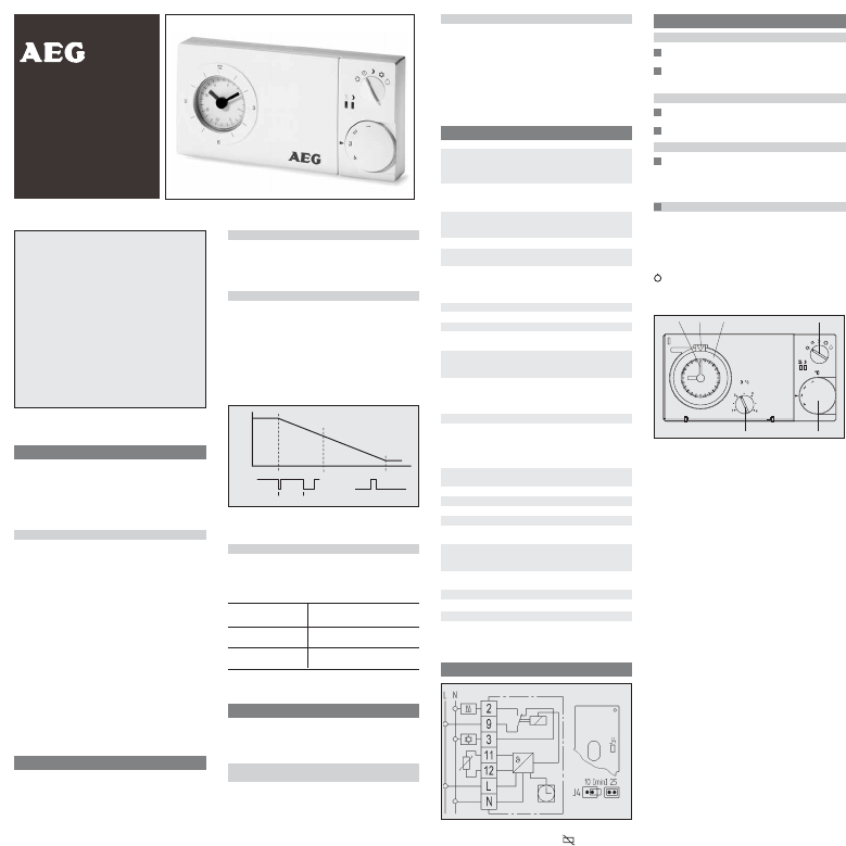
1. Applications
The FTEU 601 electronic clock thermostat is designed
for floor temperature control in conjunction with:
•
electric floor heating systems
•
hot-water floor heating systems
•
etc.
Features
•
very simple operation
•
comfort and setback temperature adjustable
•
5 operating modes (by rotary switch) for:
➩ permanent comfort temperature (10…40°C)
➩ permanent setback temperature (10…40°C)
➩ clock mode (automatic)
➩ frost protection (10°C fixed)
➩ OFF
• Indicator lamps for:
➩ heat demand
➩ setback mode
•
available with daily or weekly timer
•
output signal PWM (cycle time adjustable via jumper)
•
relay output, 1 x changeover contact
•
with remote sensor for recording floor temperature
•
emergency operation at sensor failure
•
hinged cover
•
new design 2000
2. Function description
The clock thermostat is designed to control the floor
temperature.
In the automatic mode, a changeover is effected bet-
ween comfort and setback mode by the built in timer.
In setback mode the green indicator lamp lights up.
If room temperature drops below set value, heating will
start, the red indicator lamp will light up.
Indicator lamps
red indicates when controller demands heat,
green indicates when setback mode is activated.
red flashing for failure.
Operating voltage to be switched OFF and ON again.
Controller heat demand at PWM
If floor temperature drops below the set value, heating
mode will start. The controller output is in the form of pul-
ses of varying length (PWM). The length of the pulses
depends on the difference between set and actual room
temperature.
The sum of pulse and pause times can be selected with
J 4 (between 10 or 25 min).
If there are large temperature differences, the controller
will switch ON or OFF permanent, e.g. when changing
over to temperature setback mode.
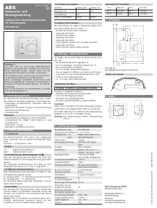
Fig. 1: Characteristic of impulse pause ratio depending
on temperature
Cycle time setting
For inert applications (e.g. burners) we recommend the
long cycle time.
For quick applications (e.g. electric direct heaters) we
recommend the short cycle time.
Plug-in jumper J4 Time
(right side of board)
Double-pole jumper 25 min
connection
Single-pole jumper 10 min (as-delivered condition)
connection
3. Installation
The controller should be arranged in a place within the
room which is easily accessible for operation.
Mounting directly on conduit box.
Electric connection
Warning! disconnect electric circuit from supply.
Proceed as follows:
•
pull off temperature setting knob
•
push retaining hook outwards using screwdriver
•
remove housing cover
•
make connection in compliance with wiring diagram
(see housing cover).
On
Off
Temperature
15/25 min
set temperature
Remote sensor
The remote sensor is extendable to max. 50 m, using a
230 V cable.
The remote sensor should be installed into a protection
tube (pocket). This facilitates later replacement.
Warning!
Sensor cables carry operating voltage.
In case of failure (break or short-circuit) the controller
switches into emergency operation and heating capacity
will be 30%.
4. Technical data
Temperature setting range:
comfort temperature
1…4 (
^
=10…40°C)
setback temperature 1…4 (
^
=10…40°C)
frost protection approx. 10°C fixed
Regulation proportional controller
(due to PWM quasi-conti-
nuous, see Fig. 1)
Cycle period adjustable 10 or 25 min.
(sum of PWM ON and OFF
times)
Proportional band 1.5 K
Output relay, 1 volt-free* changeover
contact
Switching current 10 mA…16 A cos ϕ = 1
max. 4 A cos ϕ = 0,6
max. 10 electro-thermal
actuators
Operating voltage 195…253 V AC 50/60 Hz
Power consumption < 1.5 W
Switching voltage 24…250 V AC
Mode selector switch comfort/automatic /setback/
frost protection/OFF
Indicator lamp:
red: controller demands heat
green: setback mode
Remote sensor: Length 4 m,
can be extended to max. 50 m
sensor characteristics 42 kΩ at 20 °C
26 kΩ at 30 °C
Range limitaiton inside setting knob
Clock:
accuracy <10 min./ year
switching time setting every 15 min. with daily timer
every hour with weekly timer
power reserve approx. 100 h
Protection class
of housing IP 30
Degree of protection II (see Warning!)
Software class A
Degree of polution 2
Calculation impulse voltage 2,5 kV
Temperature for the
Ball compression test 75°C
Voltage and Current for the
purposes of interfernce
measurements 230V, 16A
Ambient temperature –10…40°C,
without condensation
Storage temperature –25…65°C
Dimensions 160 x 80 x 36 mm
Weight approx. 220 g
* The volt-free contact of this mains-operated unit
does not ensure the requirement for the use of safe-
ty extra-low voltage (SELV).
5. Wiring diagram
Symbol explanation
U Heating P Cooling Remote sensor
6. Operation
Temperature setting
Comfort temperature (daytime temperature)
is set by means of externally visible setting knob (1)
Setback temperature (night temperature)
is set by means of adjustment knob (2) beneath cover.
Time setting
by putting one finger on dial (3) and turning in any
direction, you can set the time.
Arrow (4) points to the selected time.
Switching time setting
Bring movable tappets (5) into required position using
a pointed object.
Outer ring = comfort temperature
Inner ring = setback temperature
Mode selector switch (6) – externally
É Comfort temperature, permanent
2 Automatic mode, time-controlled changeover
between comfort and setback temperature
Setback temperature, permanent
P Frost protection, permanent (10°C)
OFF, there is no control activity. The controller itself is
not disconnected from operating voltage.
12
4 5 6
3
Ñ
6
5
4
3
2
1
Warning!
This unit must not be opened and installed ex-
cept by authorized persons and in compliance
with the circuit diagram provided inside the
cover. It is mandatory in all work on the unit to
observe the current safety regulations.
In order to classify for protection class II it is
necessary to take adequate installation mea-
sures.
This separately mounted unit is designed for
temperature control exclusively in dry and clo-
sed rooms with standard environment. The
device confirms to EN 60730, it works accord-
ing operating principle 1C
U 468 931 002 980-2
Instructions for use
and assembly
Electronic
Clock Thermostat
FTEU 601
Errors possible-subject to alterations 280923/34615/2/0743


Diskutieren Sie über dieses Produkt mit
Hier können Sie uns Ihre Meinung zu AEG FTEU 601 Thermostat mitteilen. Wenn Sie eine Frage haben, lesen Sie zunächst das Bedienungsanleitung sorgfältig durch. Die Anforderung eines Bedienungsanleitung kann über unser Kontaktformular erfolgen.
Antworten | Das war hilfreich (0) (Übersetzt von Google)